L+
1
4
brn
blk
NC
2
wht
3
M
Q1/Q1/C
blu
5
MF
gra
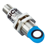
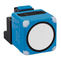
Figure 5: Male connector, M12, 5-pin
Table 2: Pin assignment UC40-xxxxxB
Contact Signs Wire color Description
1 L+ Brown Supply voltage, see "Mechanics/Electronics",
page 36
2 N/C White Not assigned
3 M Blue Supply voltage: 0 V
4 Q 1/Q1/C Black Digital output 1, IO-Link communication
5 MF Gray Multifunction input (MF), synchronization and
multiplex operation, communication via Con‐
nect+ software
UC40-xxxxxH
L+
1
4
brn
blk
Q
A
/Q2/Q2
2
wht
3
M
Q1/Q1/C
blu
5
MF
gra
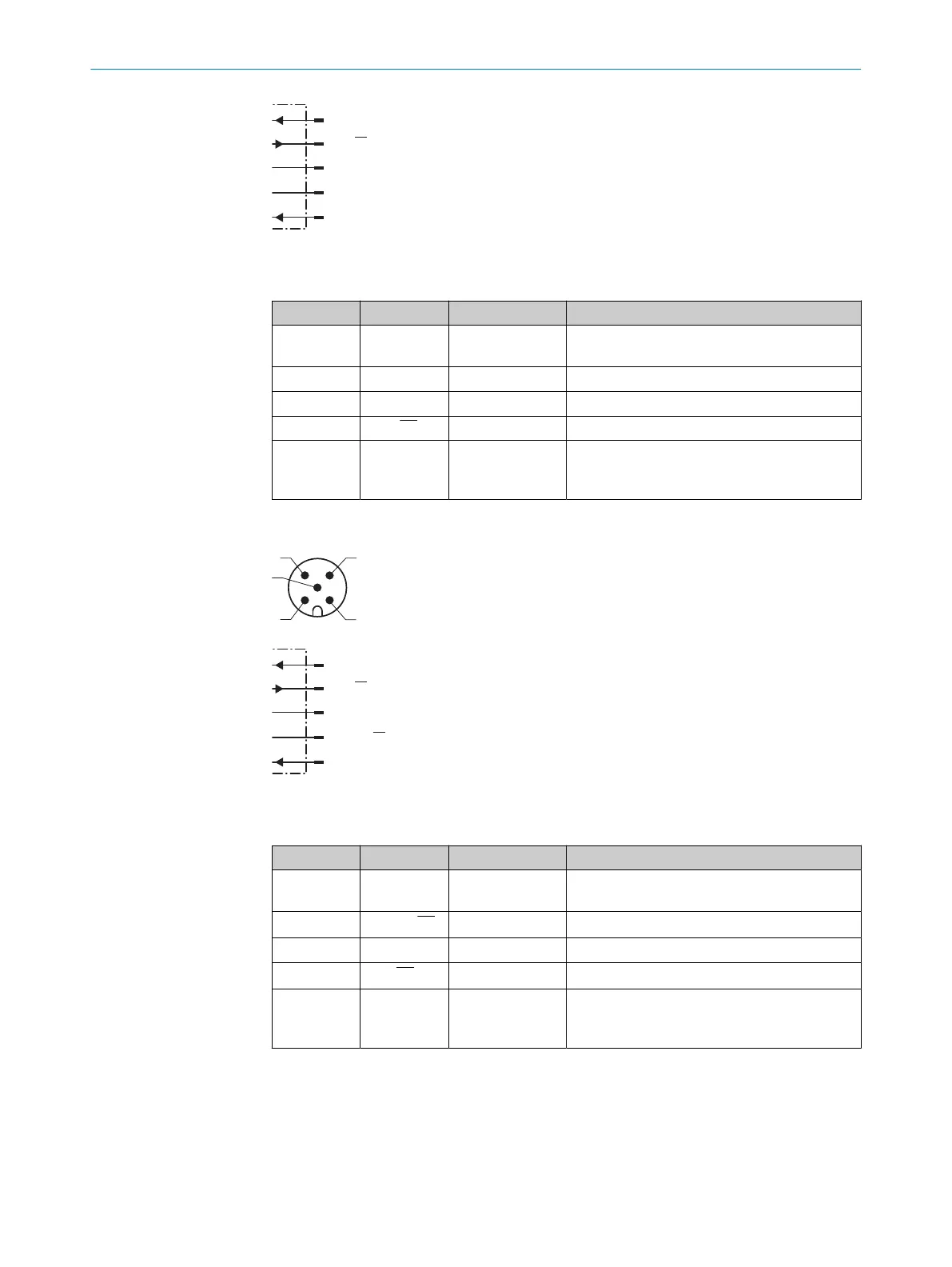
Figure 6: Male connector, M12, 5-pin
Table 3: Pin assignment UC40-xxxxxH
Contact Signs Wire color Description
1 L+ Brown Supply voltage, see "Mechanics/Electronics",
page 36
2 Q
A
/Q2/Q2 White Analog output or digital output 2
3 M Blue Supply voltage: 0 V
4 Q1/Q1/C Black Digital output 1, IO-Link communication
5 MF Gray Multifunction input (MF), synchronization and
multiplex operation, communication via Con‐
nect+ software
6 ELECTRICAL INSTALLATION
20
O P E R A T I N G I N S T R U C T I O N S | UC40 8027772//2022-08-11 | SICK
Subject to change without notice
 Loading...