Approach
1. Switch off the supply voltage.
2. Ensure that connected hardware is not damaged by the 24 V output voltage.
3. Press and hold the T2 pushbutton.
4. Press and hold the T2 pushbutton to switch on the supply voltage.
5. Press and hold T2 for 6 seconds until LED 4 lights up and LED 3 flashes.
✓
LED 4 lights up green.
✓
LED 4 flashes orange 1x: device automatically selects current or voltage output
(factory setting).
✓
LED 4 flashes orange 2x: voltage output.
✓
LED 4 flashes orange 3x: current output.
✓
LED 4 flashes orange 4x: push-pull digital output.
6. To change the setting, press T2 for 1 second.
7. Wait 10seconds.
✓
The pin 2 output is set. The device automatically switches to normal operation
mode.
7.3.2 Digital output1 teach-in
7.3.2.1 Factory settings of the digital output
•
N/O contact
•
Switching point at maximum operating range
7.3.2.2 Teaching in switching point (Single Point Mode)
Overview
When the object is located below the taught-in switching point, the digital output is
active.
Approach
Teaching in the switching point (distance to object as switching point)
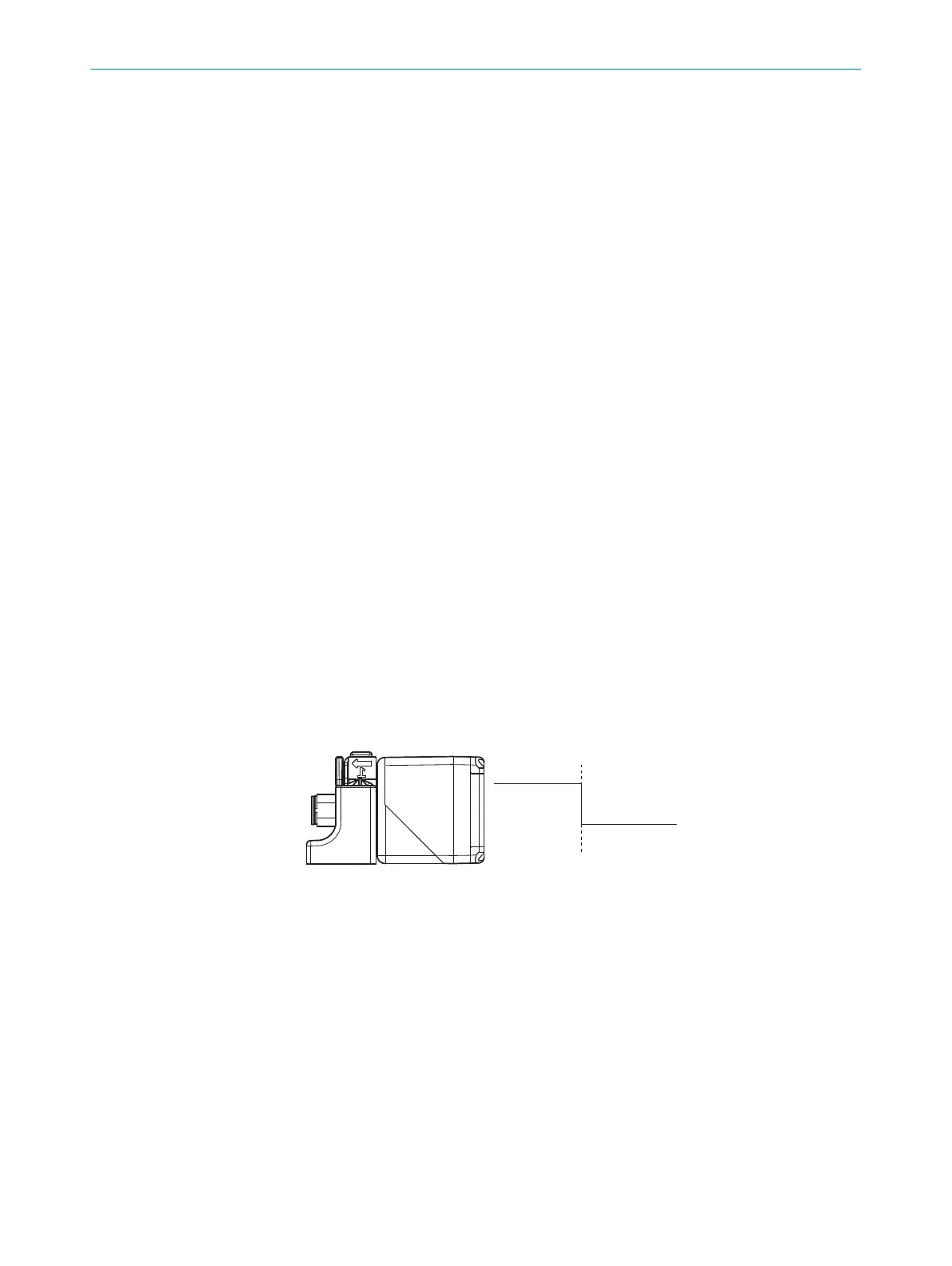
1.
Position the object at 1.
2. Press T2 pushbutton for 3 seconds until LED 1 and LED 2 flash simultaneously.
✓
LED 1 and LED 2 flash alternately.
3. Press T2 for 1 second.
✓
The switching point is taught in. The device automatically switches to normal
operation mode.
Teaching in switching point (distance to object + 8% as switching point)
1.
Position the object at 1.
2. Press T2 pushbutton for 3 seconds until LED 1 and LED 2 flash simultaneously.
✓
LED 1 and LED 2 flash alternately.
3. Press T2 for 3 seconds until LED 1 and LED 2 flash alternately again.
✓
The switching point is taught in. The device automatically switches to normal
operation mode.
7
OPERATION
22
O P E R A T I N G I N S T R U C T I O N S | UC40 8027772//2022-08-11 | SICK
Subject to change without notice
 Loading...