4. Press T1 for 1 second.
✓
The switching points are taught in. The device automatically switches to normal
operation mode.
7.3.3.4 Teaching in background (Window Mode ±8%)
Overview
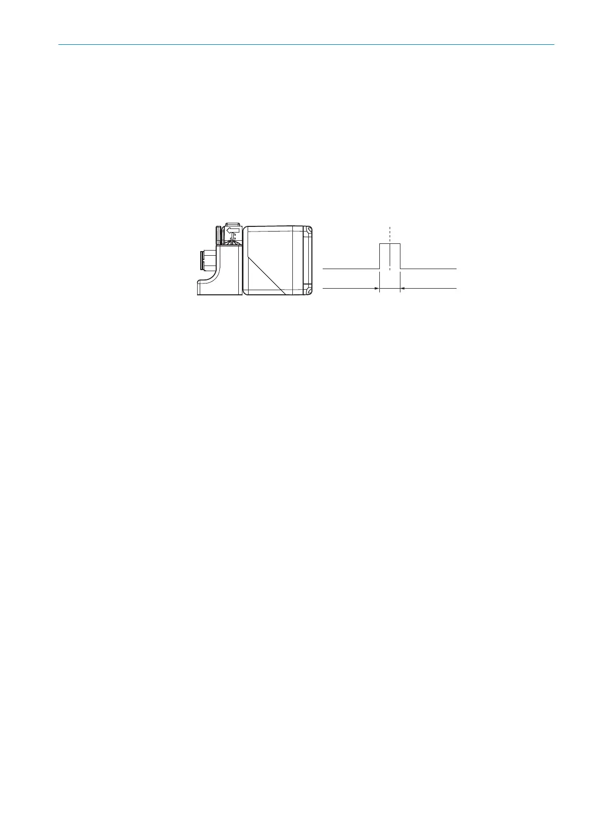
When the object is located either below the taught-in reflector -10mm (IO-Link: -8%) or
above the taught-in reflector +10mm (IO-Link: +8%), the digital output is active.
Approach
1.
Position the background at 1.
2. Press T1 pushbutton for 3 seconds until LED 3 and LED 4 flash simultaneously.
✓
LED 3 and LED 4 flash alternately.
3. Press T1 for 10 seconds until LED 3 and LED 4 stop flashing.
✓
The background is taught in. The device automatically switches to normal opera‐
tion mode.
7.3.3.5 Adjusting the N/C contact and N/O contact
Approach
1. Press T1 pushbutton for 13 seconds until LED 3 and LED 4 flash alternately.
✓
LED 3 flashes orange.
✓
N/O contact: LED 4 lights up green.
✓
N/C contact: LED 4 does not light up.
2. To change the setting, press T1 for 1 second.
3. Wait 10seconds.
✓
N/C and N/O are adjusted. The device automatically switches to normal operation
mode.
7.3.4 Analog output teach-in (UC40-xxxxxH only)
7.3.4.1 Factory settings of the analog output
•
Rising output characteristic from minimum to maximum operating range
7.3.4.2 Scaling analog output
Overview
To scale the analog output, teach in a close sensor and distant sensor scaling limit. If
the distant sensor scaling limit is taught in first and then the close sensor scaling limit,
the limits are reversed internally.
Approach
Teaching in the scaling limits
OPERATION 7
8027772//2022-08-11 | SICK O P E R A T I N G I N S T R U C T I O N S | UC40
25
Subject to change without notice
 Loading...