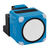
7.4.3.3 Teaching in switching window (Window Mode)
Overview
When the object is located within the taught-in switching window, the digital output is
active.
Approach
1.
Position the object at 1.
2. Apply M at MF for 3seconds until both LED 3 and LED 4 are flashing simultaneously.
✓
LED 3 and LED 4 flash alternately.
3.
Position the object at 2.
✓
LED 3 and LED 4 flash alternately.
4. Apply M at MF for 1second.
✓
The switching points are taught in. The device automatically switches to normal
operation mode.
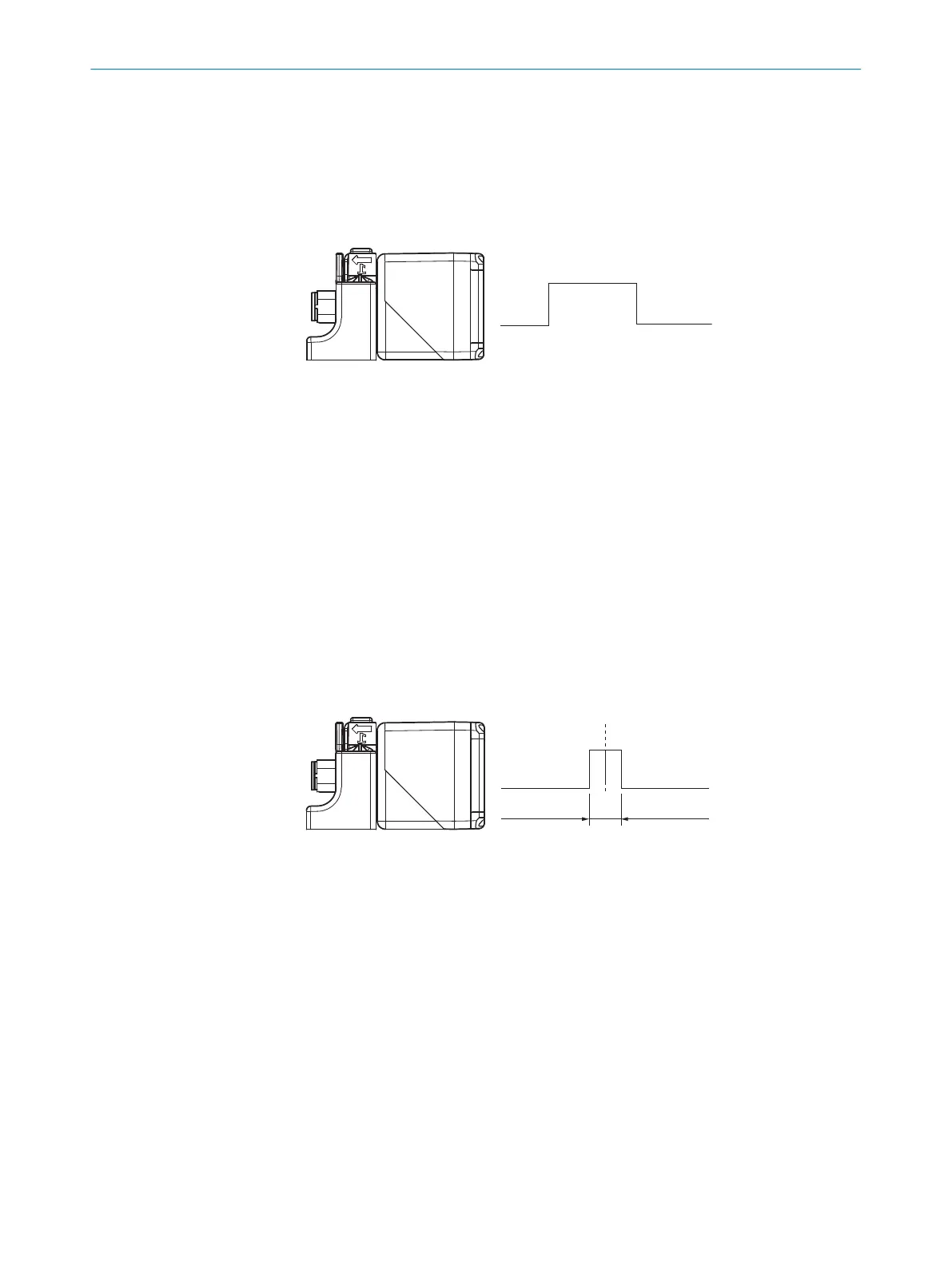
7.4.3.4 Teaching in background (Window Mode ±8%)
Overview
When the object is located either below the taught-in reflector -10mm (IO-Link: -8%) or
above the taught-in reflector +10mm (IO-Link: +8%), the digital output is active.
Approach
1.
Position the background at 1.
2. Apply M at MF for 3seconds until both LED 3 and LED 4 are flashing simultaneously.
✓
LED 3 and LED 4 flash alternately.
3. Apply M at MF for 10 seconds until LED 3 and LED 4 stop flashing.
✓
The background is taught in. The device automatically switches to normal opera‐
tion mode.
7.4.3.5 Adjusting the N/C contact and N/O contact
Approach
1. Apply M at MF for 13seconds until both LED 3 and LED 4 flash alternately.
✓
LED 3 flashes orange.
✓
N/O contact: LED 4 lights up green.
✓
N/C contact: LED 4 does not light up.
2. To change the setting, apply M at MF for 1second.
3. Wait 10seconds.
✓
N/C and N/O are adjusted. The device automatically switches to normal operation
mode.
7 OPERATION
30
O P E R A T I N G I N S T R U C T I O N S | UC40 8027772//2022-08-11 | SICK
Subject to change without notice
 Loading...