■
The cables plugged into the connections are screwed tight.
If these instructions are not complied with, the IP enclosure rating for the device is not
guaranteed!
5.2 Notes on UL approval
The device shall be supplied from an isolating transformer having a secondary overcur‐
rent protective device that complies with UL 248 to be installed in the field rated either:
a) max 5 amps for voltages 0 ~ 20 V (0 ~ 28.3 V peak), or
b) 100 / Vp for voltages of 20 ~ 30 V (28.3 ~ 42.4 V peak).
Alternatively, they can be supplied from a Class 2 power supply.
UL Environmental Rating: Enclosure type 1
5.3
Connection notes
Operation in standard I/O mode:
– Male connector connection: Pin assignment
– Cable: Wire color
Only apply voltage and switch on the voltage supply once all electrical connections have
been established.
Operation in IO-Link mode: Connect the device to a suitable IO-Link Master. Integrate
into the master or into the controller using IODD/function block. The green LED flashes
on the sensor. IODD and function block are available to download from www.sick.com
under the part number.
Explanation of the connection terminology used in the following tables:
•
BN = brown
•
WH = white
•
BU = blue
•
BK = black
•
Q/Q = digital output
•
C = IO-Link
•
MF = multifunctional input/output
•
L+ = supply voltage (U
V
)
•
M = ground
DC: 10 ... 30V DC, see "Technical data", page 47
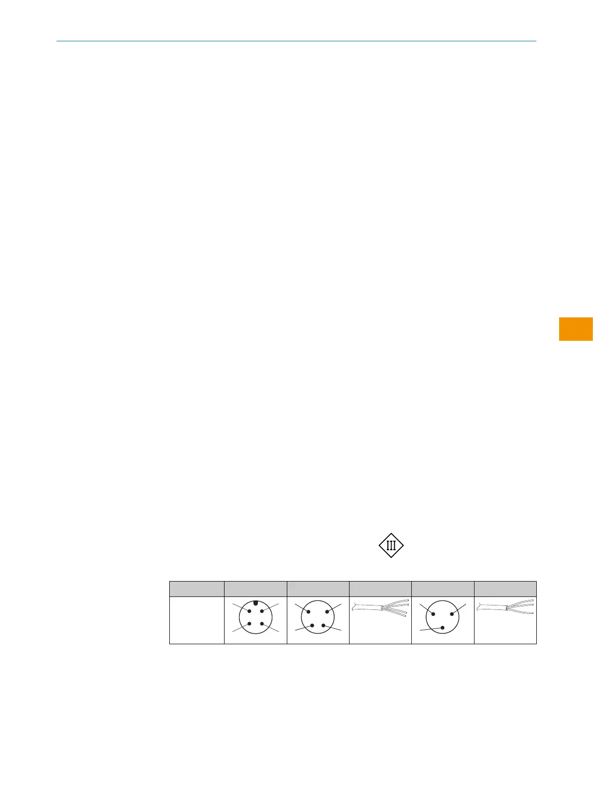
Table 2: Electrical connection
Wxx4Sx- x4 x2 xH x1 xG
1 = BN
2 = WH
3 = BU
4 = BK
0.14mm
2
AWG26
0.14mm
2
AWG26
OPERATING INSTRUCTIONS
80282151N09/2024-03-12 | SICK O P E R A T I N G I N S T R U C T I O N S | WLG4S
35
Subject to change without notice
en