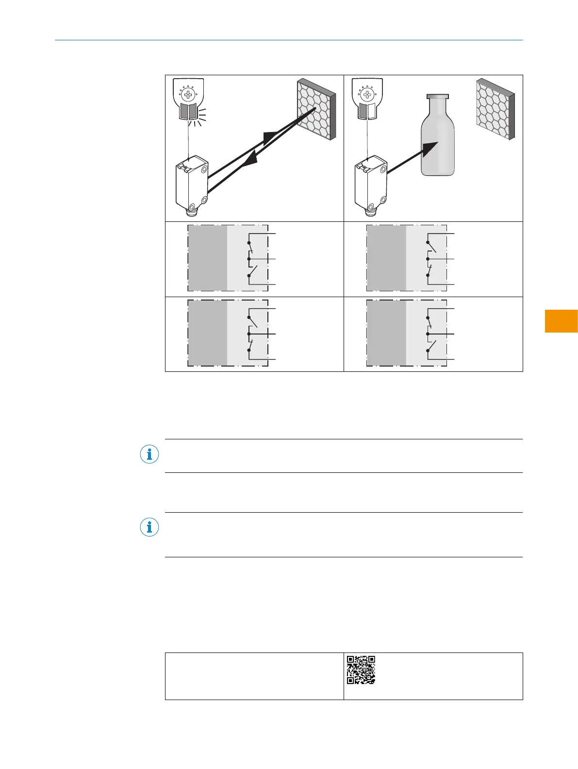
Table 5: Push-pull, PNP, NPN
Push-pull
PNP
NPN
+ (L+)
Q ≤ 100 mA
‒ (M)
Push-pull
PNP
NPN
+ (L+)
Q ≤ 100 mA
‒ (M)
Push-pull
PNP
NPN
+ (L+)
Q ≤ 100 mA
‒ (M)
Push-pull
PNP
NPN
+ (L+)
Q ≤ 100 mA
‒ (M)
5.4 Integration of the sensor in IO-Link mode
To operate the product in IO-Link mode, it must be connected to a suitable IO-Link
Master. This is used for further integration into the control system.
NOTE
The cable length between the IO-Link Master and IO-Link device: maximum 20m.
Details on integration can be found in the detailed IO-Link description: Technical Infor‐
mation: Photoelectric sensors, SICK Smart Sensors / IO-Link.
NOTE
After successful connection of the product to the IO-Link Master, the green (Power) LED
flashes to indicate a functioning IO-Link communication between the master and device.
6 Commissioning
6.1 Videos
The following tutorial shows how to commission the sensor:
Table 6: Video overview
Selecting MultiMode operating mode and teach‐
ing in the sensor
https://video.sick.com/media/t/0_cxzr6xi1
OPERATING INSTRUCTIONS
80282151N09/2024-03-12 | SICK O P E R A T I N G I N S T R U C T I O N S | WLG4S
37
Subject to change without notice
en