NOTE TIP:
Should switching errors nevertheless arise due to extremely depolarizing objects, the
WLG4S can also be adapted to these extreme conditions and the switching errors
suppressed by means of a teach-in (via IO-Link or using the teach-in button on the
housing).
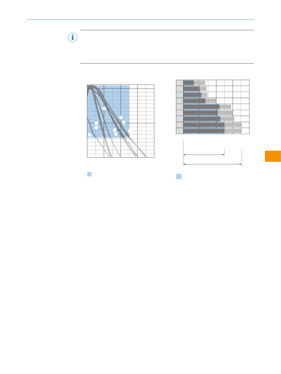
Table 7: Diagrams of distance between the sensor and reflectors
WLx4SP-xxxxxx30xxx, WLx4SP-xxxxxx20xxx, standard reflectors:
0
100
10
1
Operating reserve
Distance in m (feet)
2
(6.56)
4
(13.12)
6
(19.69)
8
(26.25)
Recommended sensing range for
the best performance
1
2
3
4
8
9
5
6
7
Figure 5: WLx4SP-xxxxxx30xxx, WLx4SP-
xxxxxx20xxx, standard reflectors
1
PL40A Antifog
2
PL20A
3
PL22-2
4
P250H
5
P250
6
PL30A
7
PL40A
8
C110A
9
PL80A
9
7
8
6
4
5
3
1
2
0
Distance in m (feet)
2
(6.56)
4
(13.12)
6
(19.69)
8
(26.25)
0
0
0
5.0 7.1
4.5
0 4.4 5.8
0 4.2 6.0
6.2
0 2.7 4.0
0 2.2 2.9
0 2.0 2.8
0 1.3 2.7
5.0 7.1
Recommended sensing range for
the best performance
D
C
A B
Figure 6: WLx4SP-xxxxxx30xxx, WLx4SP-
xxxxxx20xxx, standard reflectors
A Sensing range min. in m
B Sensing range max. in m
C Maximum distance range from
reflector to sensor (operating
reserve 1)
D Recommended distance range from
reflector to sensor (operating
reserve 3.75)
blue Recommended sensing range for
the best performance
WLx4SP-xxxxxx30xxx, WLx4SP-xxxxxx20xxx, reflective tape:
OPERATING INSTRUCTIONS
80282151N09/2024-03-12 | SICK O P E R A T I N G I N S T R U C T I O N S | WLG4S
39
Subject to change without notice
en