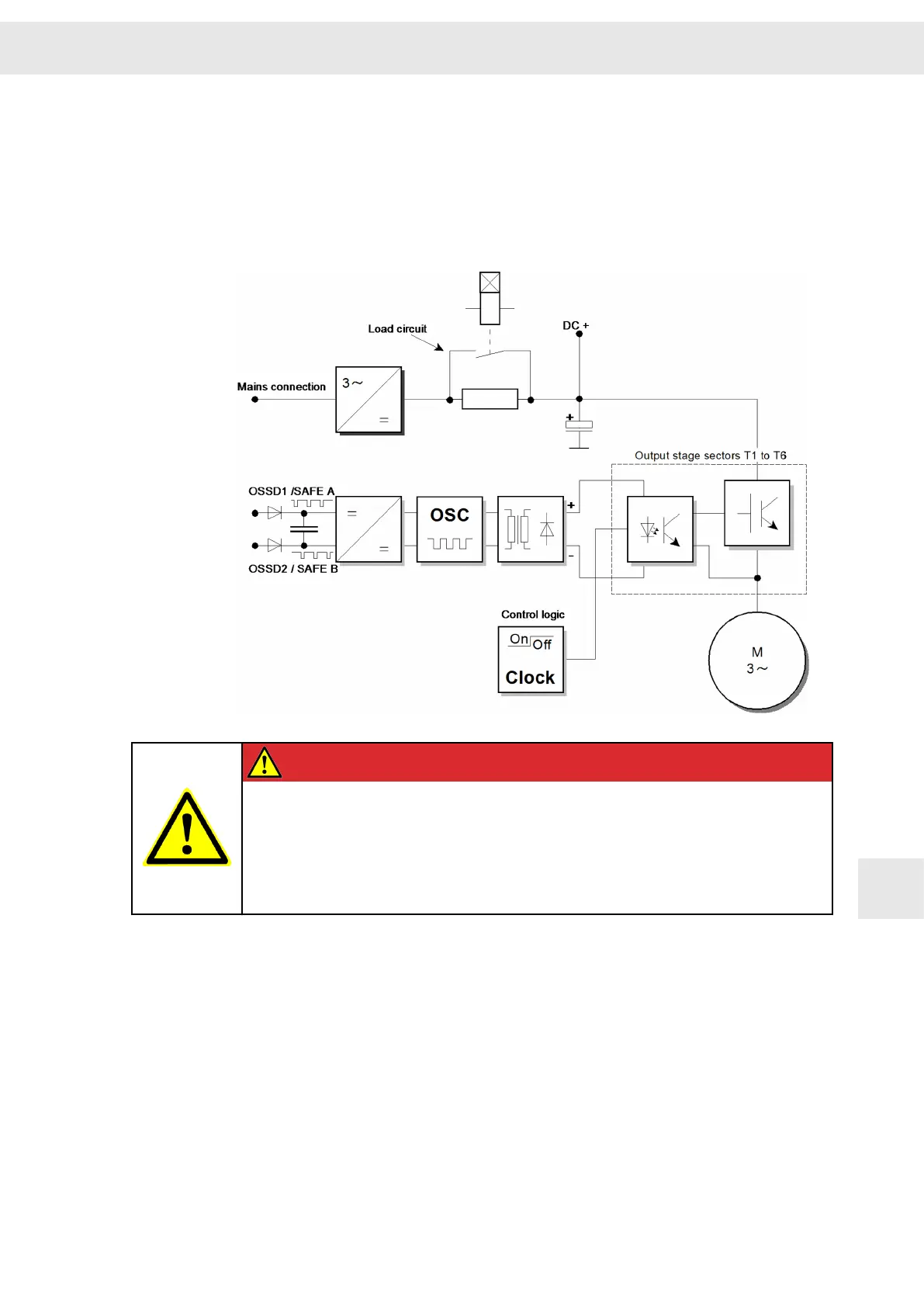
If the OSSD signals or at least one of the +24 V conductors fail, the safety circuit
switches the pulse pattern of the output stage control sectors off. The response time of
the restart lock is max. 4 ms.
The restart lock must only be controlled when
▶ the drive is at a secure standstill (stop category 2),
▶ the higher-ranking control has deactivated the drive module,
▶ (reference speed value 0)
▶ the holding brake of the motor has been arrested.
DANGER
No torque when restart lock is active
The motor cannot provide a torque when the restart lock is activated. Thus non-
self-locking drives could be released.
Non-self-locking drives as hanging loads must be blocked with a mechanical
brake.
12.2 Wiring Example
Combining a safe emergency stop command device, an OSSD safety switch device or
a light barrier with OSSD outputs and the safe switching off of the pulse patterns allows
creation of an error detection circuit, which achieves a safe stop (according to stop
function category 0+1), which meets the safety requirements according to SIL 3 (EN
ISO 13849-1). This circuit allows connecting several emergency stop devices in
parallel, which are permanently monitored.
W
Safety Circuit / Restart Lock (STO)
Drive System SD2S - Hardware Description 0362X49xy / 0362129xy 97
12
 Loading...

