7 Connector Pin Assignment
7.1 Operation of the Terminal Connectors
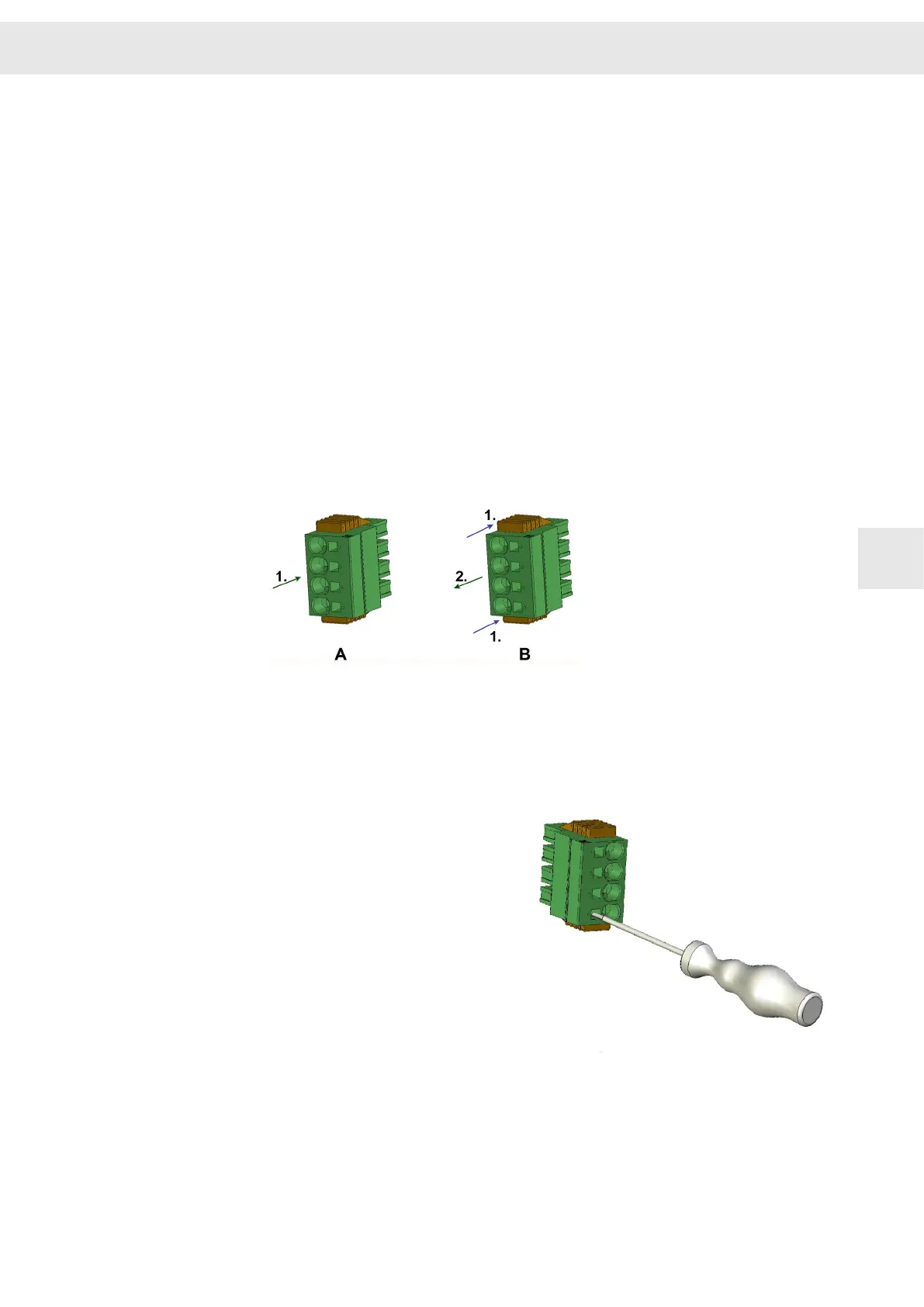
7.1.1 Click & Lock System (STCL Connectors)
Plugging the connector [A]
▶ Plug the connector as shown in the figure on the housing and ensure that the
connector locks in place (1.).
Note: Both side guides must be fully pushed back to ensure that the connector
locks firmly in place and to prevent unwanted loosening of the connector (e.g. in
case of vibrations).
Removing the connector [B]
▶ Move the two side guides of the connector as shown in the figure toward the
device (1.) and unplug the connector (2.).
Fig. 6: Plug [A] and unplug the connector [B]
7.1.2 Push-in Technology
Terminals using the push-in connection
technology (PIT) work on the pressure
spring principle:
The contact spring presses the cable
against the conducting copper bar. The
special spring profile allows direct and
tool-free wiring of solid and stranded
cables previously assembled with
ferrule or compressed conductor ends.
▶ When the cable is inserted into the
clamping unit the spring opens
automatically.
▶ To open the clamp and loosen the
cable use a screw driver.
7.2 ID switch
➮ Set the address for the module by means of the address selection switch.
16 adresses are available: 0, 1, 2, 3, 4, 5, 6, 7, 8, 9, A, B, C, D, E, F.
W
Connector Pin Assignment
Drive System SD2S - Hardware Description 0362X49xy / 0362129xy 37
7
 Loading...

