Connector Pin Assignment
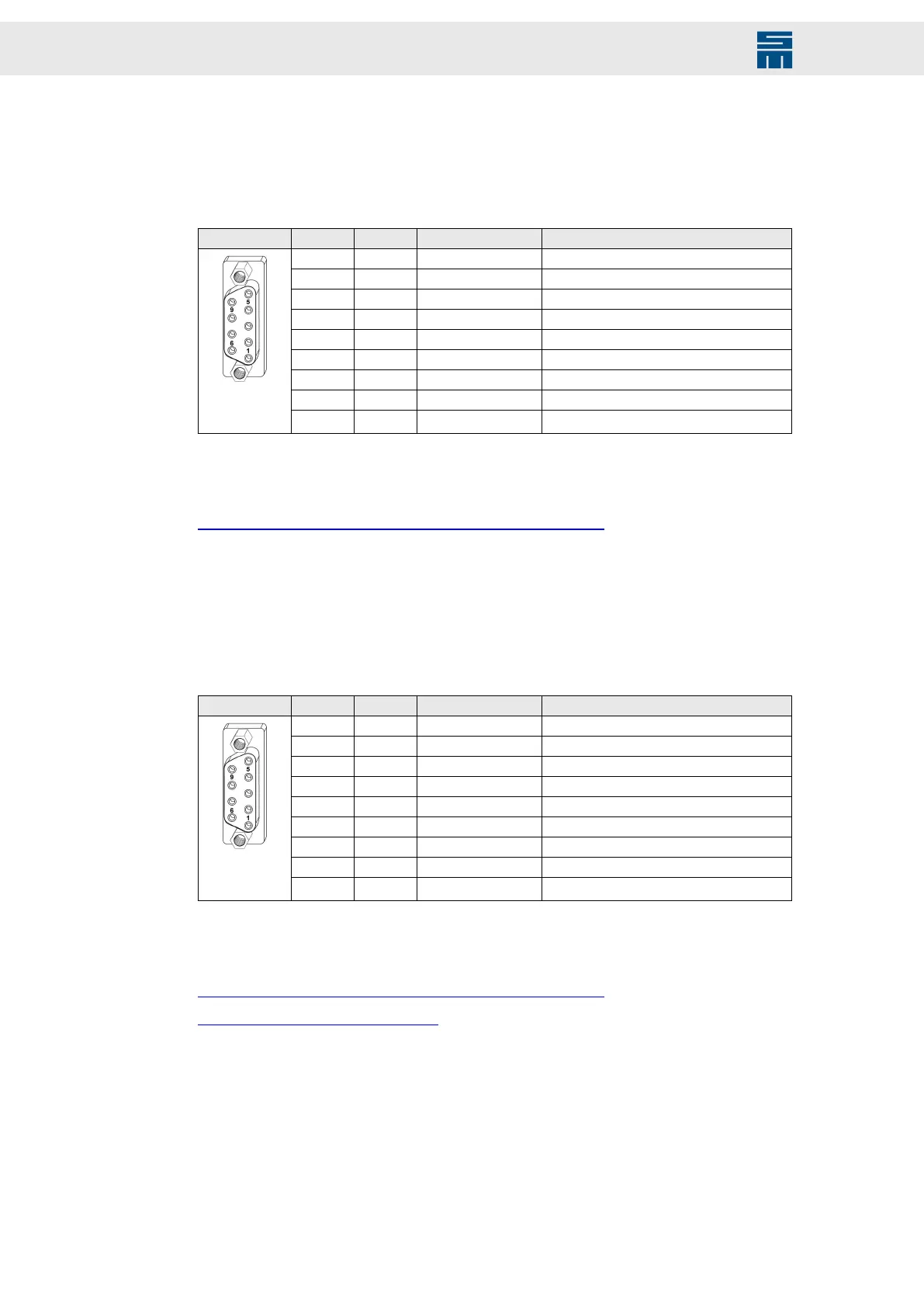
12.7 X6 – Encoder 0
Encoder 0 input, e.g. for length measuring systems
9-pole female submin D connector
X6 Pin I/O Name Meaning
1 I UA+ Track A+
2 I UA- Track A-
3 I UN+ Zero pulse+
4 I UN- Zero pulse-
5 I/O GND Ground
6 I UB+ Track B+
7 I UB- Track B-
8 O VCC_ENC 5.3 V supply voltage
9 n.c. Do not connect!
Locking bolts flange: max. tightening torque = 0.7 Nm
Related topics
X6, X7 – Incremental Encoders with TTL Signals, page 135
12.8 X7 – Encoder 1 / Encoder Emulation
Encoder 1 input and encoder emulation output e.g. for depth measuring systems
9-pole female submin D connector
X7 Pin I/O Name Meaning
1 I/O UA+ Track A+
2 I/O UA- Track A-
3 I/O UN+ Zero pulse+
4 I/O UN- Zero pulse-
5 I/O GND Ground
6 I/O UB+ Track B+
7 I/O UB- Track B-
8 O VCC_ENC 5.3 V supply voltage
9 n.c. Do not connect!
Locking bolts flange: max. tightening torque = 0.7 Nm
Related topics
X6, X7 – Incremental Encoders with TTL Signals, page 135
X7 – Encoder Emulation, page 136
112 Drive System SD2 - Hardware Description