6.3 Device Variant 0362111OF (max. 160 A) with
Integrated Water-cooled Heat Sink
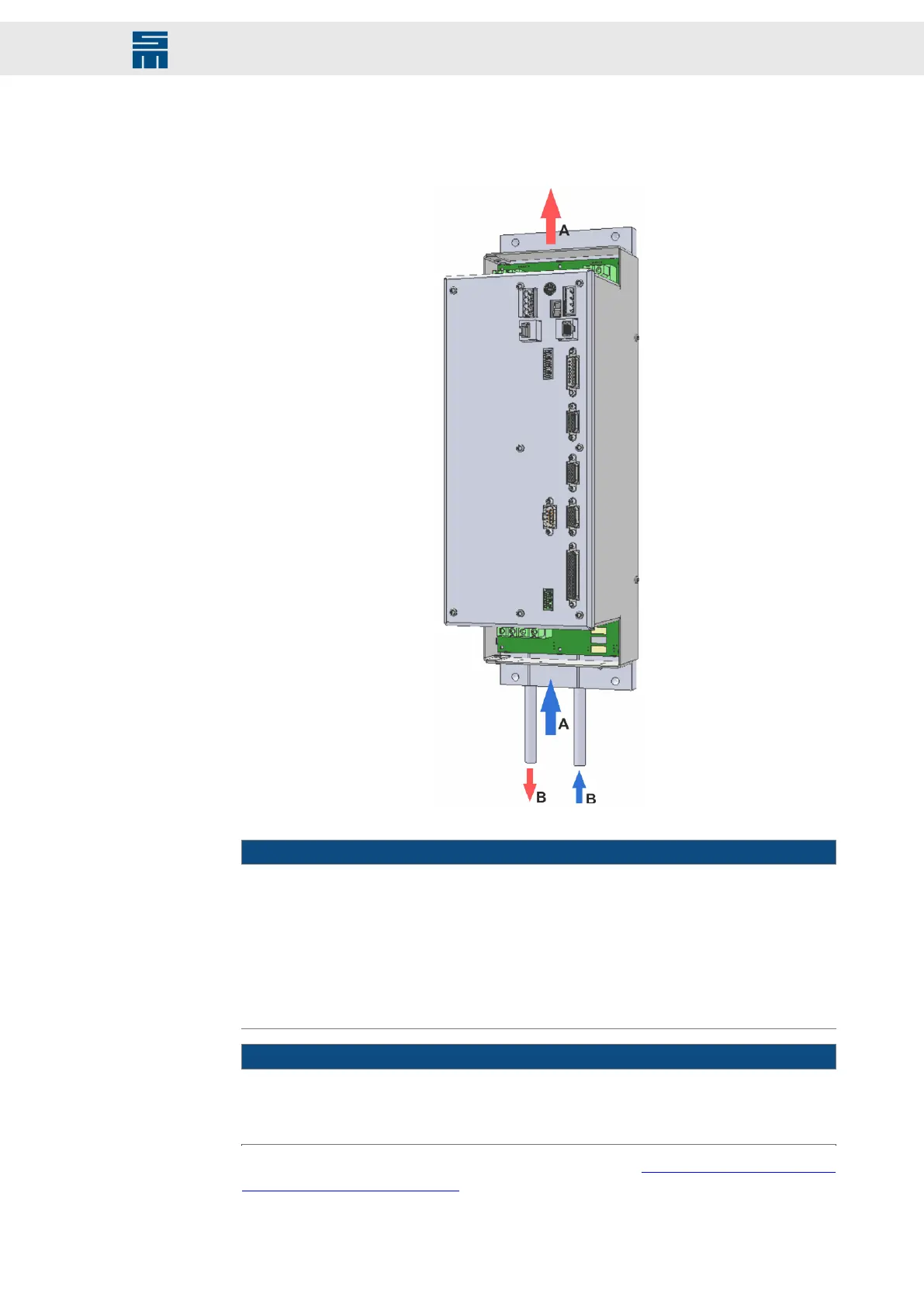
Fig. 11: Device view 0362111OF with direction of air flow (A) and cooling circuit (B)
Fig. 11: Device view 0362111OF with direction of air flow (A) and cooling circuit (B)
NOTICE
Restriction of cooling air flow
If the air flow cooling the device is obstructed, the device could overheat and possibly
become damaged.
→ When installing the device, pay attention to the direction of air flow through the in-
ternally installed fan [arrows A].
→ For sufficient cooling the ventilation inlets and outlets must be kept free by a space
of min. 10 cm.
NOTICE
Wrong flow direction of the coolant
→ For optimal cooling, consider the flow direction of the coolant during mounting. In-
stall the forward and return flow of the coolant according to the arrows [B].
For further information on the water cooling refer to chapter 11 “Water Cooling
(0362111OF/RF/SF)”, page 105.
33Drive System SD2 - Hardware Description
Single-axis Drive Amplifiers