12.14 X13– Analog Interface
The available functions of the analog inputs and outputs are different depending on the
drive function. You can set the desired function in the software drivemaster2.
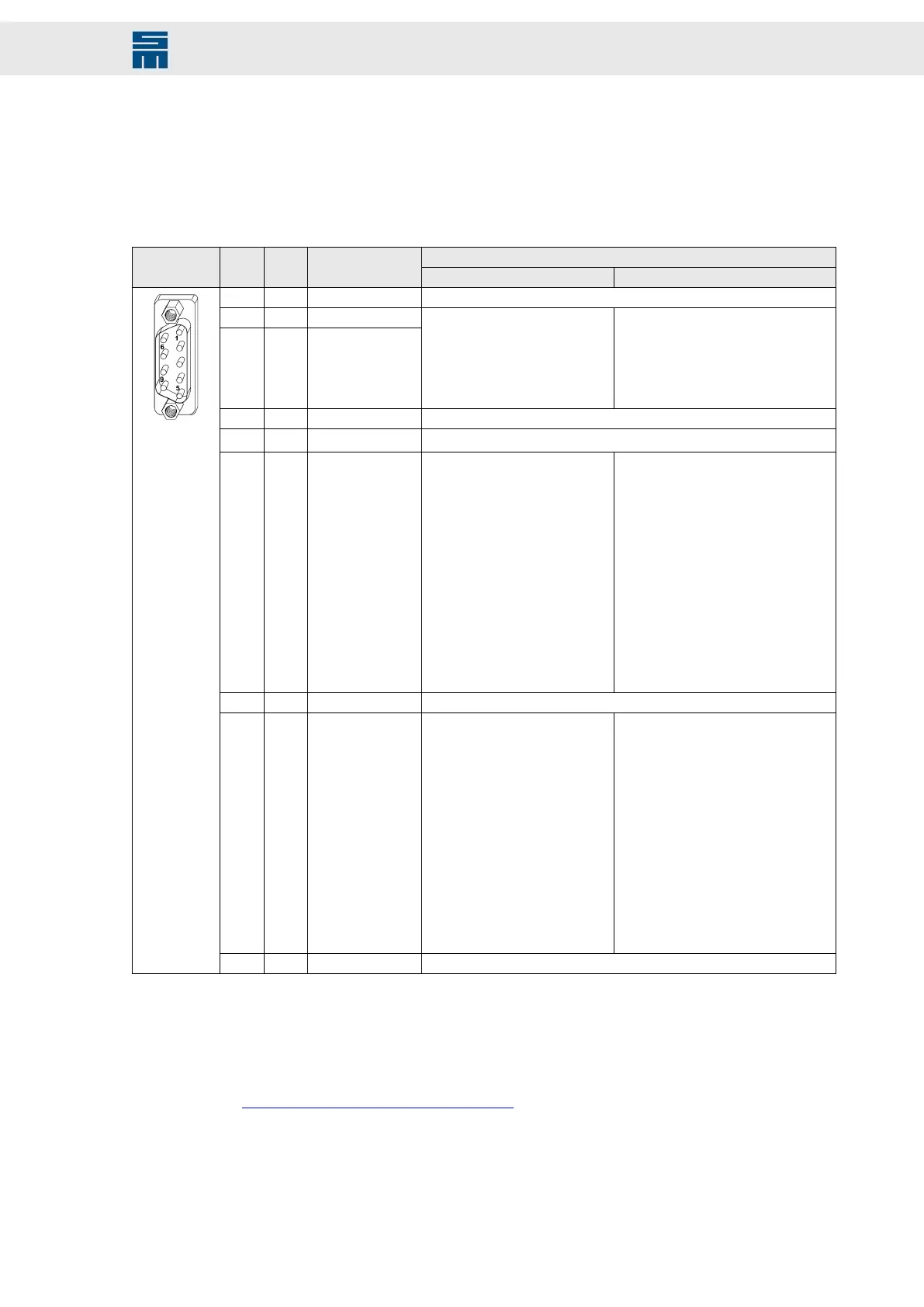
9-pole male submin D connector
Configurable functionsX13 Pin I/O Name
SERVO / VECTOR (SVC) VF
1 I AIN1- Reference point of AIN1+ (pin 2)
2 I AIN1+
3 I AIN0+
▸
No function
▸
Speed reference value
▸
Current reference value
▸
Current limitation
▸
W24 – Warning threshold
’current'
▸
No function
▸
Speed reference value
▸
Current limitation
▸
W24 – Warning threshold ’current'
4 I/O GND Ground
5 n.c.
6 O
AOUT1
(1)
▸
No function
▸
Target speed
▸
Speed reference value
▸
Speed actual value
▸
Speed error
▸
Current reference value
▸
Current actual value
▸
Motor temperature
▸
Power output stage tempera-
ture
▸
Motor load
▸
Power output stage load
▸
Voltage of the bus
▸
Active power
▸
DC link current Idc
▸
No function
▸
Target speed
▸
Speed reference value
▸
Speed actual value
▸
Speed error
▸
Current reference value
▸
Current actual value
▸
Motor temperature
▸
Power output stage temperature
▸
Motor load
▸
Power output stage load
▸
Voltage of the bus
▸
Active power
▸
DC link current Idc
7 I AIN0- Reference point for AIN0+ (pin 3)
8 O
AOUT0
(1)
▸
No function
▸
Target speed
▸
Speed reference value
▸
Speed actual value
▸
Speed error
▸
Current reference value
▸
Current actual value
▸
Motor temperature
▸
Power output stage tempera-
ture
▸
Motor load
▸
Power output stage load
▸
Voltage of the bus
▸
Active power
▸
DC link current Idc
▸
No function
▸
Target speed
▸
Speed reference value
▸
Speed actual value
▸
Speed error
▸
Current reference value
▸
Current actual value
▸
Motor temperature
▸
Power output stage temperature
▸
Motor load
▸
Power output stage load
▸
Voltage of the bus
▸
Active power
▸
DC link current Idc
9 O VCC_5 +5.3 V supply voltage
(1)
The analog outputs are available with device version 9.100 and higher.
Locking bolts flange: max. tightening torque = 0.7 Nm
Related topics
X13 – Analog Inputs/Outputs, page 149
117Drive System SD2 - Hardware Description
Connector Pin Assignment