Single-axis Drive Amplifiers
6.4.3 Connectors
The housing changes from July 2019 are gray-col-
ored.
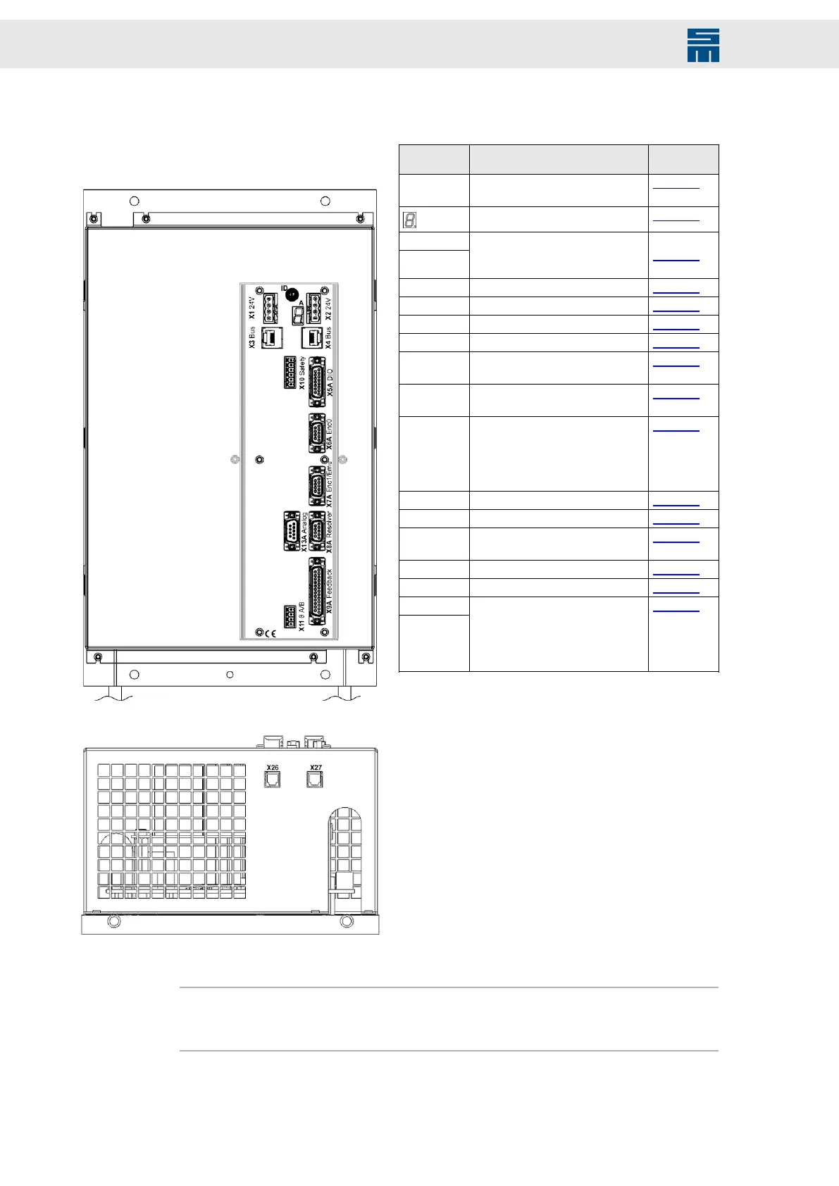
Fig. 17: Front view
Fig. 17: Front view
Fig. 18: Bottom view
Fig. 18: Bottom view
Connector Meaning Descrip-
tion
ID Address selection switch of de-
vice
page 107
A
Status display page 156
X1 24 V
X2 24 V
Power bus: 24 V logic supply and
status message from the power
supply
page 107
X3 Bus Bus inputs page 108
X4 Bus Bus outputs page 108
X5A DIO Digital inputs / digital outputs page 109
X6A Enc0 Encoder 0 input page 112
X7A Enc1/
Emu
Encoder 1 input / Emu output page 112
X8A Re-
solver
Resolver page 113
X9 A Feed-
back
Sine cosine encoder / incremen-
tal encoder TTL / Hall encoder /
linear Hall encoder / field plate
sensor / EnDat encoder / SSI en-
coder / Hiperface encoder
page 114
X10 Safety Safety circuit / restart lock (STO) page 115
X11ϑ A/B Temperature sensor of the motor page 116
X13A Ana-
log
Analog signals page 117
X26 SERVOLINK 4 optical input page 122
X27 SERVOLINK 4 optical output page 122
DC link
Motor phas-
es
The connectors for the motor (U,
V, W) and the DC link (+UB,−UB)
are located under the device cov-
er. Therefore, you should wire
these connectors at first.
page 127
Note
You can order the suitable connector kit for the device variant 0362111RF at
SIEB & MEYER under article number 32299578.
40 Drive System SD2 - Hardware Description