Safety circuit / restart lock (STO)
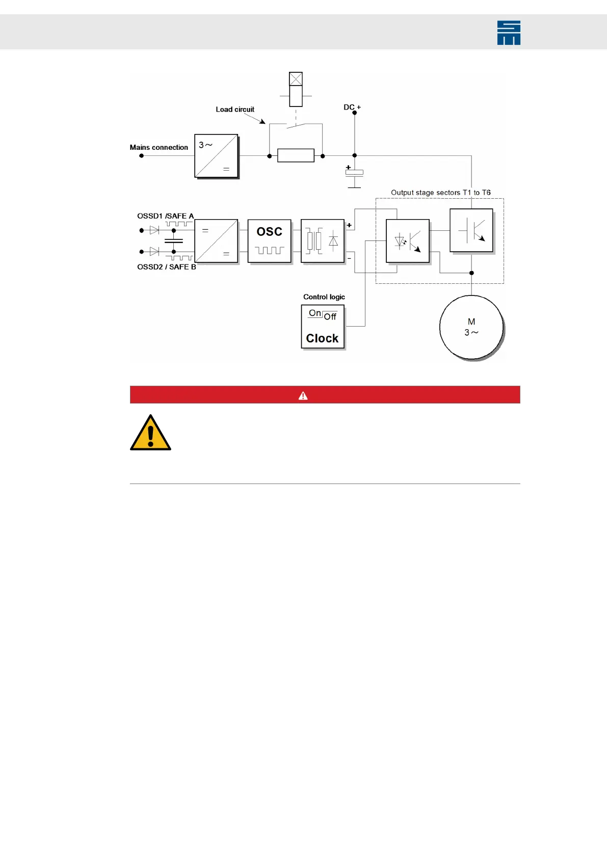
Fig. 96: Safety circuit control
Fig. 96: Safety circuit control
DANGER
No torque at restart lock activated
The motor cannot provide a torque when the restart lock is activated. Thus
non-self-locking drives could be released.
→ Non-self-locking drives as hanging loads must be blocked with a me-
chanical brake.
19.2 Wiring Example
Combining a safe emergency stop command device, an OSSD safety switch device or
a light barrier with OSSD outputs and the safe switching off of the pulse patterns al-
lows creation of an error detection circuit, which achieves a safe stop (according to stop
function category 0+1), which meets the safety requirements according to SIL 3 (EN
ISO 13849-1). This circuit allows connecting several emergency stop devices in parallel,
which are permanently monitored.
178 Drive System SD2 - Hardware Description