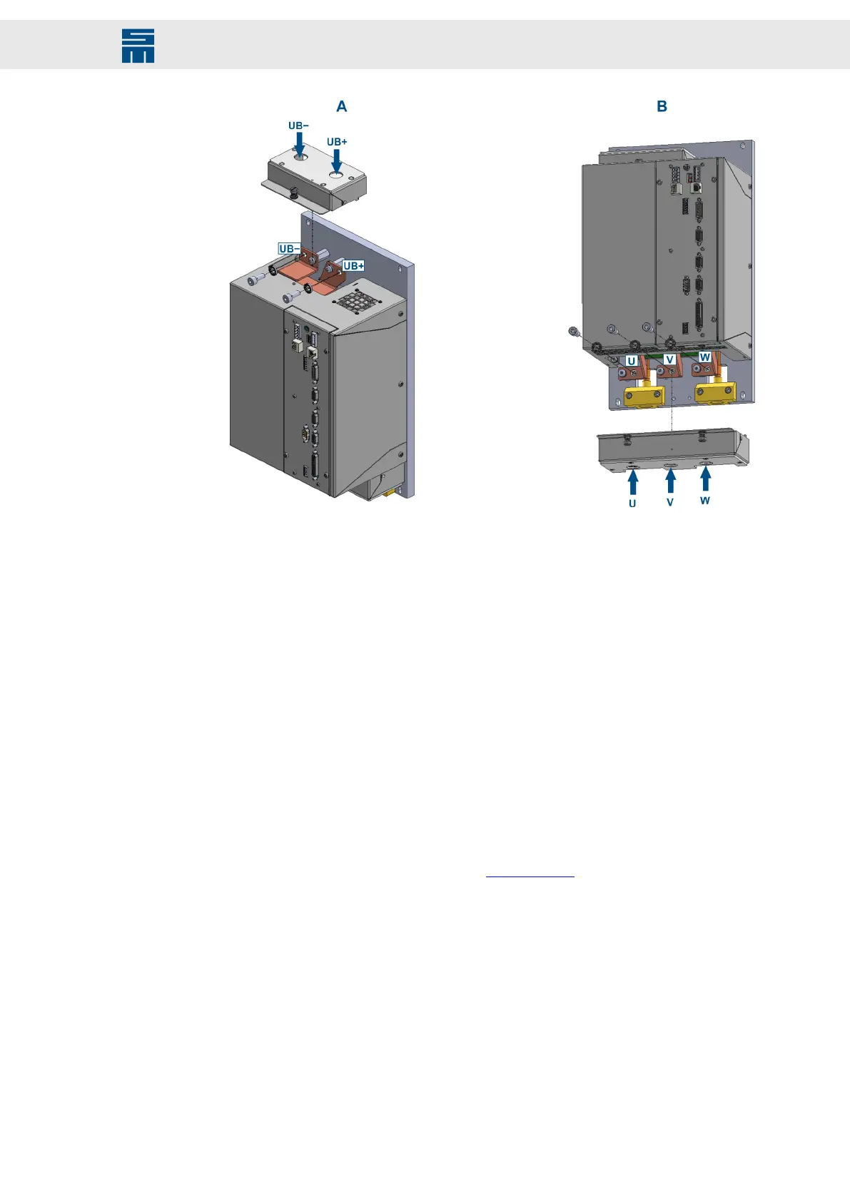
➮ Loosen the quick-release bolt at the top of the device and take the connector cover
off [picture A]. The DC link connections are flat copper bars with drill holes.
➮ Feed the DC link cables (UB+, UB−) through the top connector cover accord-
ing to the arrows in the picture. Then, connect the cables using ring cable lugs
[picture A].
a. bolt size = M8
b. tightening torque = 23 Nm
➮ Loosen the 2 quick-release bolts at the bottom of the device and take the connector
cover off [picture B]. The motor phase connections are flat copper bars with drill
holes.
➮ Feed cables for the motor phases (U, V, W) through the bottom connector cover ac-
cording to the arrows in the picture. Then, connect the cables using ring cable lugs
[picture B].
a. bolt size = M8
b. tightening torque = 23 Nm
Also refer to the connection example Motor Phases.
➮ Put the top connector cover back on the device and tighten it with the quick-release
bolt.
➮ Put the bottom connector cover back on the device and tighten it with the 2 quick-
release bolts.
131Drive System SD2 - Hardware Description
Connector Pin Assignment