Information on the application of motors
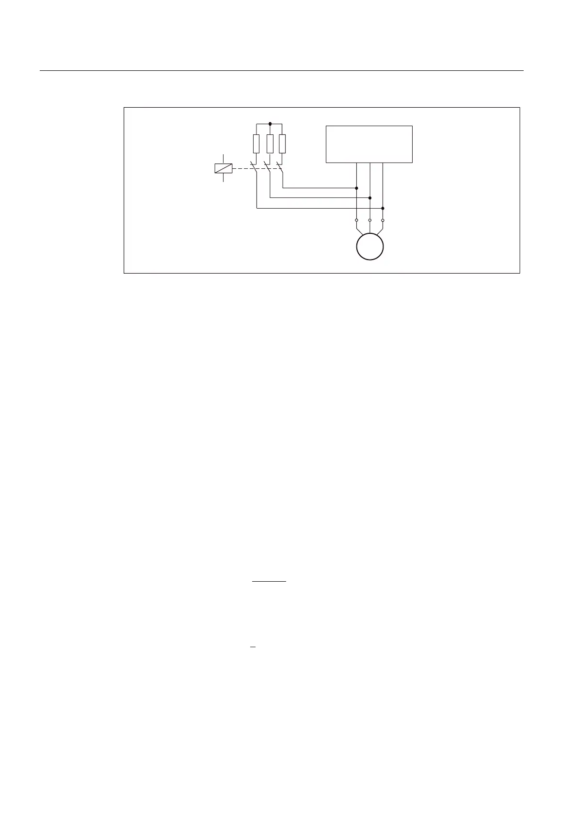
7.8 Brake resistances (armature short-circuit braking)
1FT7 Synchronous Motors
236 Configuration Manual, (PFT7S) 01/2009, 6SN1197-0AD13-0BP2
0
a
6,1$0,&6
5
EU
89:
Figure 7-3 Circuit (schematic) with brake resistors
Rating
The ratings of the resistors must match the particular I
2
t load capability. The resistors can be
dimensioned so that a surface temperature of 300° C can occur briefly (max. 500 ms). In
order to prevent the resistors from being destroyed, braking from the rated speed can occur
max. every 2 minutes. Other braking cycles must be specified when ordering the resistors.
The external moment of inertia and the intrinsic motor moment of inertia are decisive when
dimensioning these resistors.
The kinetic energy must be specified when ordering in order to determine the resistor rating.
W = ½ ∙J ∙ ω
2
W [Ws]
J [kgm
2
]
ω [s
-1
]
Braking time and deceleration distance
The braking time is calculated using the following formula:
Braking time:
W
ವ
ವ
%
1WRW
%
0
Q-
Braking time t
B
[s]
Rated speed n
N
[rpm]
Moment of inertia:
+=
JJJ
WRW
PRW IRUFHYHQWLODWHG
Average braking torque M
B
[Nm]
Moment of inertia J [kgm
2
]
Braking distance:
• =
%PD[
s t V
2
1
Braking distance s [m]
Velocity V
max
[m/s]

 Loading...


