Information on the application of motors
7.8 Brake resistances (armature short-circuit braking)
1FT7 Synchronous Motors
Configuration Manual, (PFT7S) 01/2009, 6SN1197-0AD13-0BP2
237
NOTICE
When determining the run-on distance, the friction (taken into account as allowance in M
B
)
of the mechanical transmission elements and the switching delay times of the contactors
must be taken into consideration. In order to prevent mechanical damage, mechanical end
stops should be provided at the end of the absolute traversing range of the machine axes.
0
EURSW
0
EUUPV
Q
1
0
EU
0
EURSW
0
EUUPV
Q
1
0
EU
,
EUUPV
Q
1
,
EU
Q
1
Q
1
Q
1
,
EUUPV
,
EU
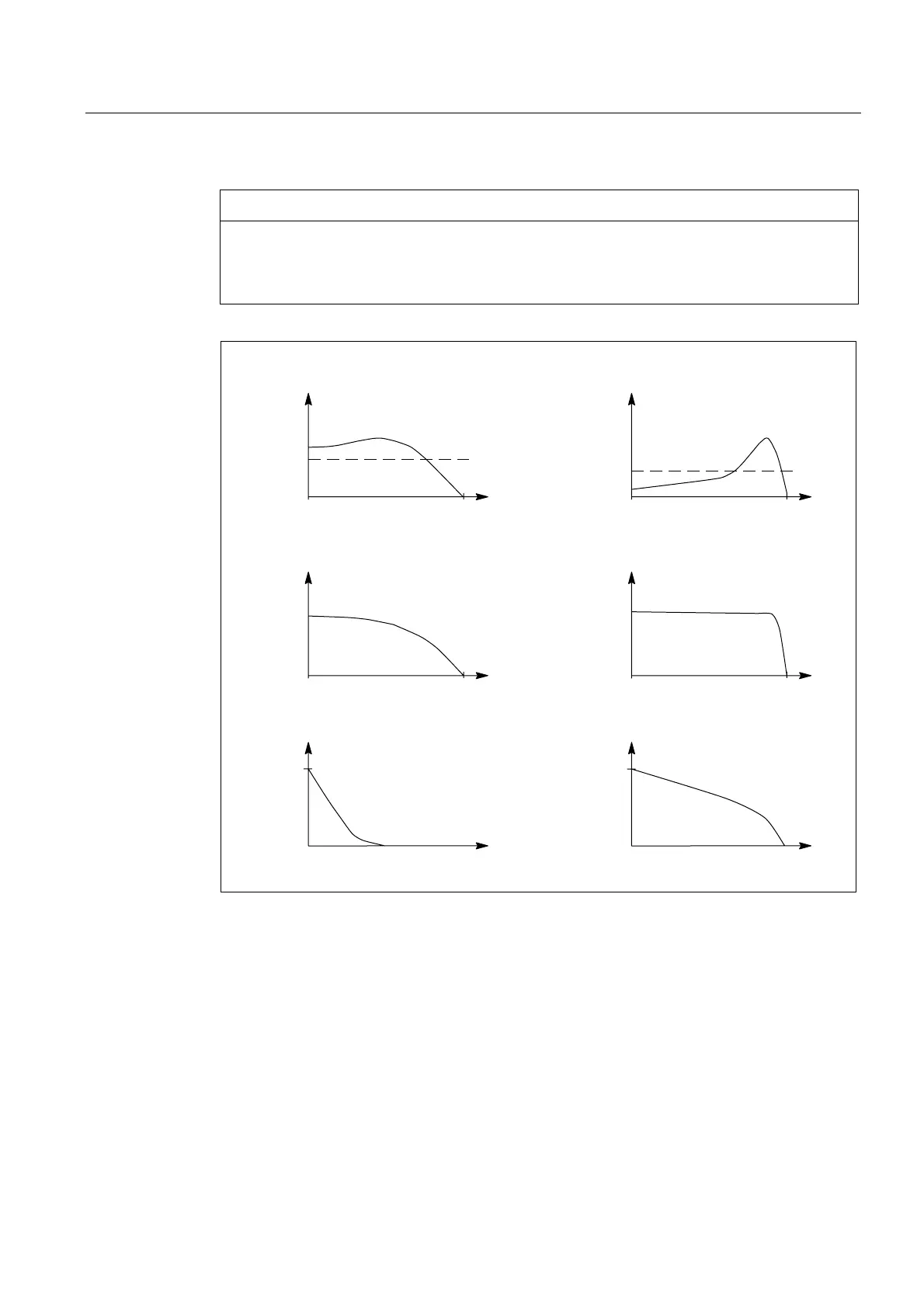
ZLWKH[WHUQDOEUDNLQJUHVLVWRU ZLWKRXWH[WHUQDOEUDNLQJUHVLVWRU
6SHHGQ
6SHHGQ
6SHHGQ
6SHHGQ
6SHHGQ
&RDVWLQJGRZQWLPHW &RDVWLQJGRZQWLPHW
6SHHGQ
Figure 7-4 Armature short-circuit braking
Dimensioning of braking resistors
The correct dimensioning ensures an optimum braking time. The braking torques which are
obtained are also listed in the tables. The data applies for braking from the rated speed and
moment of inertia J
external
= J
mot
. If the drive is braked from another speed, then the braking
time cannot be proportionally reduced. However, longer braking times cannot occur if the
speed at the start of braking is less than the rated speed.
The data in the following table is calculated for rated values according to the data sheet. The
variance during production as well as iron saturation have not been taken into account here.
Higher currents and torques can occur than those calculated as a result of the saturation.

 Loading...


