Connecting
6.9 Assignment of terminals and connectors
SINAMICS DCM DC Converter
188 Operating Instructions, 12/2018, A5E34763375A
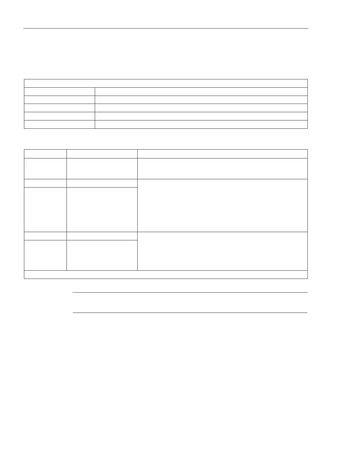
Terminal assignment functional safety
Table 6- 44 Terminal type functional safety
PUSH IN connecting terminal LMF 5.08
Min. 0.12 - 2.5 mm² / AWG 26 - AWG 12
Rigid/flexible/conductor sizes (mm²/AWG): 0.2 - 2.5 / 26 - 12, with ferrule: 0.25 ... 2.5 mm²
Stripped length 10 mm
PUSH IN screwdriver blade 0.6 x 3.5 mm according to DIN 5264 standard
Table 6- 45 Assignment of customer terminals on Allocation Board (overview)
X200-1 P24 Output 20 to 26 V, short-circuit proof
Can be continuously loaded up to 30 mA
Used for supplying X200-2, if STO is not used.
Input (both terminals are connected)
H signal (no STO):+15 V to +30 V, input current 2 mA (typical)
L signal (STO): –30 V to +5 V or terminal open
Leakage current maximum 0.5 mA
Maximum cable length: 30 m
The input must be supplied from a PELV power supply.
Test pulses are not permitted.
X200-3 STO
Feedback contact for safety relay
The contact is closed if the STO is selected.
Rated voltage 24 V, maximum current load 200 mA, leakage current
maximum 0.5 mA
Connection to diagnostic circuit of the safety relay (PELV circuit)
X201-2 RM1
"Allocation Board" module
Note
The maximum cable length that can be connected is 30
m.
 Loading...
