Additional system components
7.4 Terminal Module TM15
SINAMICS DCM DC Converter
234 Operating Instructions, 12/2018, A5E34763375A
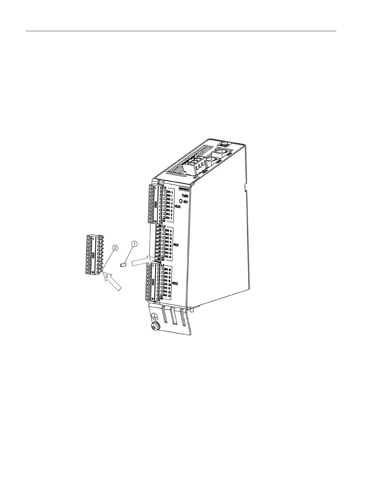
A series of coding elements ("coding sliders") are supplied with each Terminal Module
TM15.
1. Insert at least one coding slider at the required position.
2. Remove the associated coding lug at the connector.
Cut off the coding lug on the connector.
Figure 7-23 Procedure for encoding a connector
To avoid wiring errors, unique coding patterns must be defined for the connectors X520,
X521 and X522.
Possible patterns:
● 3 connectors on one component are encoded differently (i.e. X520, X521 and X522).
● Different component types are encoded differently.
● Otherwise identical components are encoded differently on the same machine,
(e.g. several TM15-type components).
 Loading...
