Accessories
7.2 Brake chopper (FSGX)
Power Module PM240
Hardware Installation Manual, 07/2009, A5E00807525B AD
103
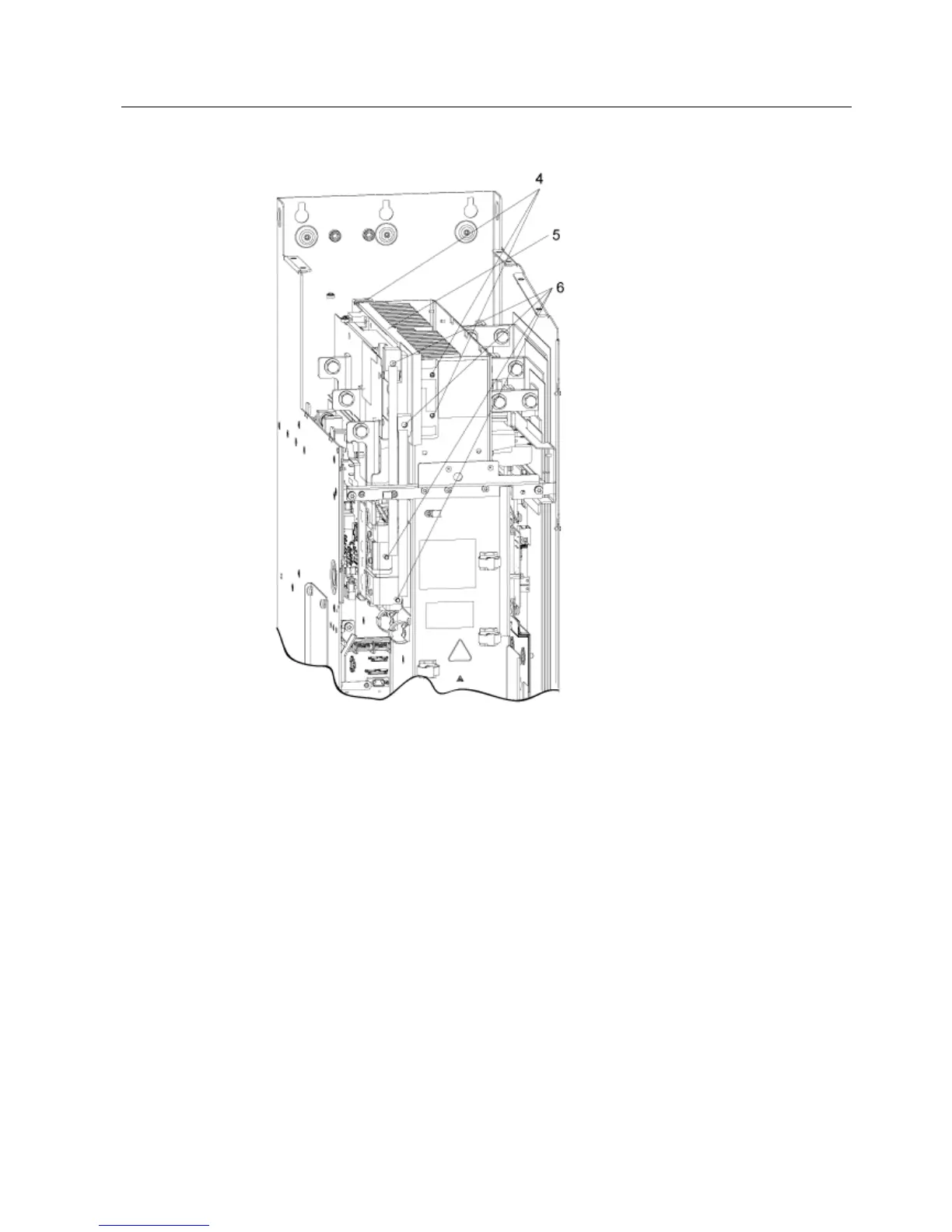
Figure 7-12 Installing the brake chopper in a Power Module FSGX – steps 4 - 6
Installing the brake chopper
The steps for the installation procedure are numbered in accordance with the figures in the
diagrams.
1. Unscrew the 2 M6 screws from the front cover and lift off the cover.
2. Unscrew the 4 screws from the upper cover plate.
Unscrew the 1 x M6 nut on the left-hand side and remove the front cover.
3. Unscrew the 4 screws from the upper cover plate.
Unscrew the 3 screws from the rear cut-out sections and remove the rear cover.
4. Unscrew the 3 screws for the blanking plate and remove the plate.
5. Insert the brake chopper where the cover used to be and secure it using the 3 screws
(from step 4).

 Loading...


