Connecting
4.1 Power distribution systems
Power Module PM240
36 Hardware Installation Manual, 07/2009, A5E00807525B AD
4.1 Power distribution systems
Overview of Power Distribution Systems
The power distribution systems described below, as defined in EN 60950 , have been
considered in the design of the inverter. In the next figures three phase systems are outlined.
The three phase inverter must be connected to L1, L2 and L3. PE must always be
connected. The inverter will operate with most supply systems.
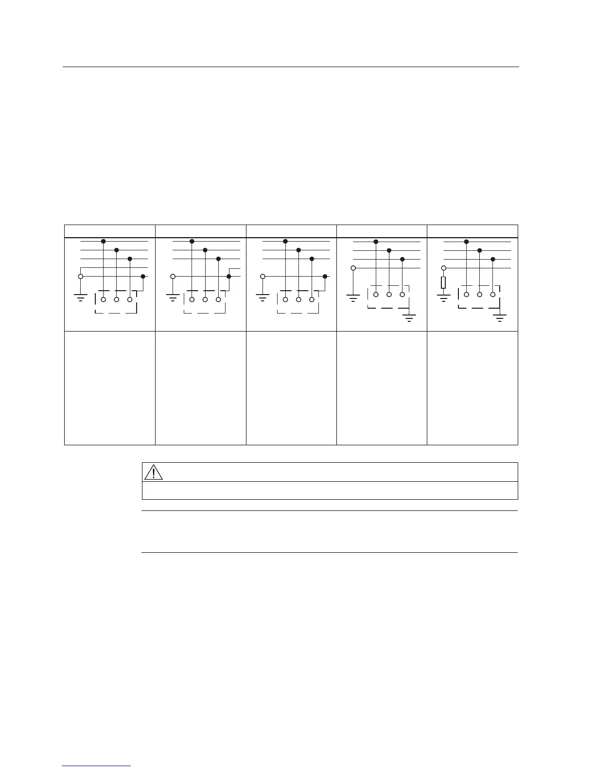
Table 4- 1 Power distribution systems
TN-S Power System TN-C-S Power System TN-C Power System TT Power System IT Power System
/
/
/
1
3(
/ / /
Exposed
Conductive Parts
/
/
/
3(
1
/ / /
1
3(
Exposed
Conductive Parts
/
/
/
1
3(
/ / /
Exposed
Conductive Parts
3(
/
/
/
1
/ / /
Exposed
Conductive
Parts
A TN-S power system
has separate neutral
and protective ground
conductors throughout
the system.
In a TN-C-S power
system, the neutral
and protective
functions are
combined in a single
part of the system.
In a TN-C power
system, the neutral
and protective
functions are
combined in a single
conductor throughout
the system.
A TT power system
has one point directly
grounded, the
exposed conductive
parts of the installation
being connected to a
ground, which is
electrically
independent of the
ground of the power
system.
An IT power system
has no direct
connection to ground -
instead the exposed
parts of the electrical
installation are
grounded.
WARNING
Filtered drives can only be used on power systems with grounded starpoint.
Note
For fulfilling the protection class I according to EN 61140 the input and output supply
voltages have to be earthed.

 Loading...


