Service and maintenance
5.2 Replacing components
Power Module PM240
56 Hardware Installation Manual, 07/2009, A5E00807525B AD
Removal
The steps for the removal procedure are numbered in accordance with the diagram.
1. Remove the retaining screws for the fan (3 screws).
2. Disconnect the supply cables (1 x "L", 1 x "N").
You can now carefully remove the fan.
CAUTION
When removing the fan, ensure that you do not damage any signal cables.
Installation
For re-installation, carry out the above steps in reverse order.
CAUTION
Carefully re-establish the plug connections and ensure that they are secure.
The screwed connections for the protective covers must only be tightened by hand.
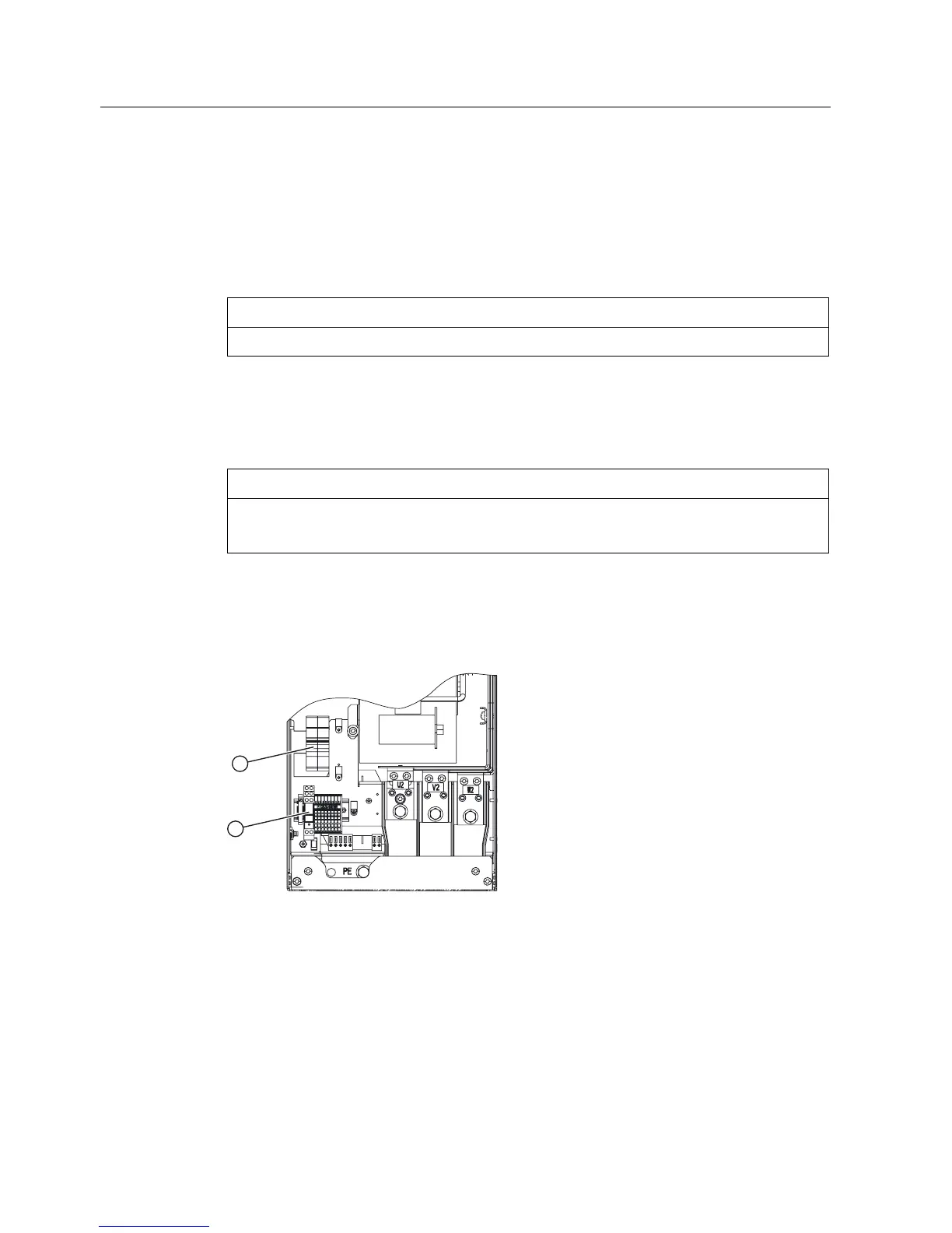
5.2.2 Replacing the cooling fan fuses and the cooling fan relay (FSGX)
Figure 5-5 Position of the cooling fan fuses ①and the fan relay ②
The cooling fan fuses and the cooling fan relay can be accessed after removing the front
cover of the Power Module FSGX.

 Loading...


