Accessories
7.3 Braking Resistor
Power Module PM240
Hardware Installation Manual, 07/2009, A5E00807525B AD
113
7.3.2 Connecting the braking resistor
The braking resistor is connected at terminals DCP/R1 and R2.
FSA ... FSF: The braking resistor can be connected directly to the Power Module.
FSGX: The connecting of a braking resistor requires the installation of a brake
chopper.
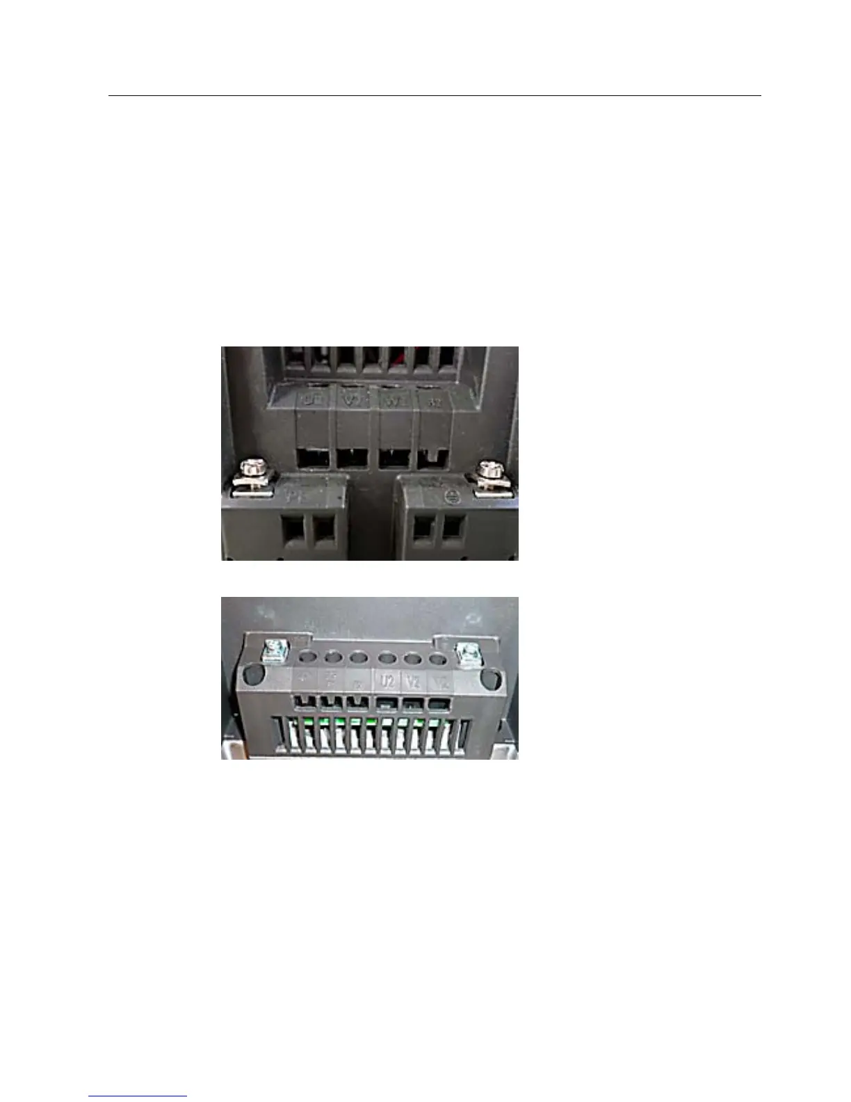
On FSA to access the R1/R2- terminals the cutout cover must be removed using a small pair
of cutters, ensuring that no plastics from the cutout fall into the inverter housing. On FSB and
FSC the R1/R2- terminals are located on the underside at the bottom of the unit (see
Figure). The terminal connection consists of up to three spades.
Figure 7-17 PM240 FSA spades
Figure 7-18 PM240 FSB spades

 Loading...


