Installing/Mounting
3.2 Dimensions and drill pattern
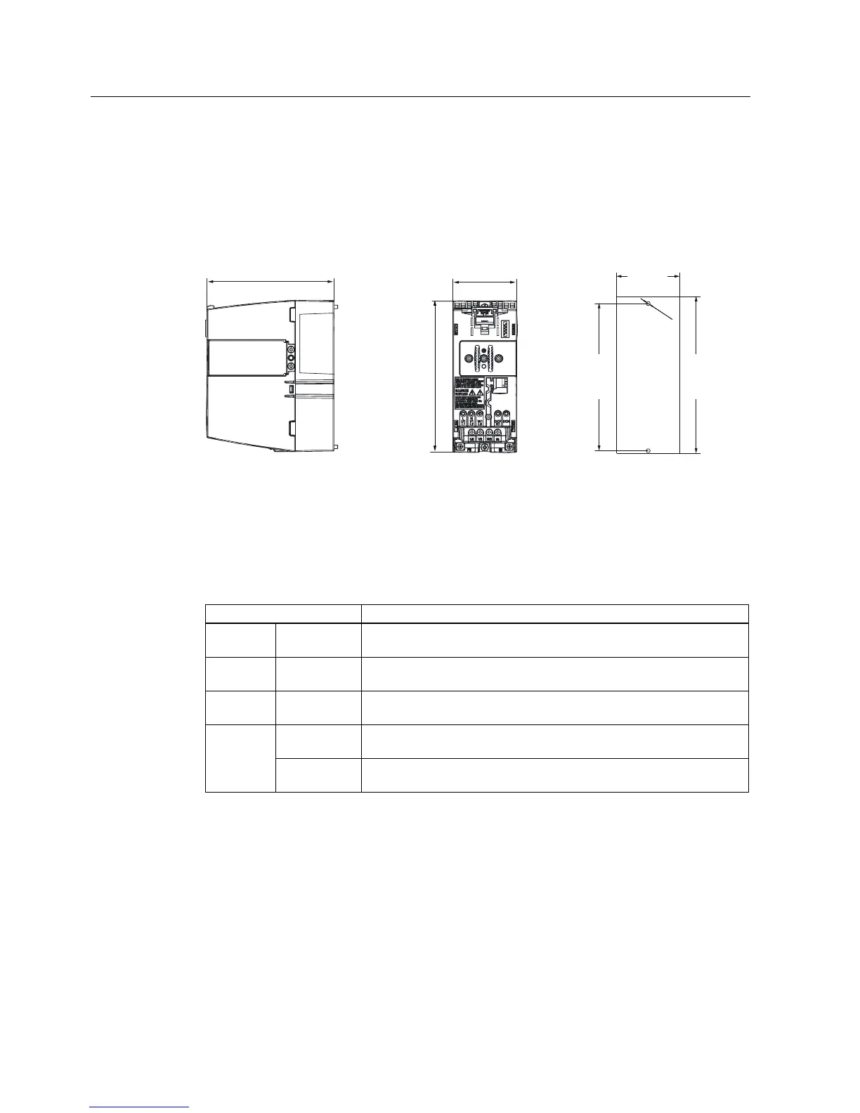
Power Module PM240
22 Hardware Installation Manual, 07/2009, A5E00807525B AD
3.2 Dimensions and drill pattern
Dimensions, drill patterns and minimum distances
The dimension drawings for all frame sizes for the SINAMICS G120 Power Module PM240
are shown in the figures and not true to scale.
)RUIL[LQJ
[0EROWV
[0QXWV
[0ZDVKHUV
7LJKWHQLQJWRUTXH1P
OEILQ
+HLJKWLQFRPELQDWLRQZLWKWKH
VFUHHQWHUPLQDWLRQNLWZR%UDNH
5HOD\
PPLQFK
PP
PP
PP
PP
PP
PP
Figure 3-2 Dimensions and drill pattern, FSA (HO 0.37 kW ... 1.5 kW)
Table 3- 3 Minimum distances for mounting
Minimum distances FSA Note
side by
side
30 mm
1.18 inches
At max. environmental temperature of 40° C (104° F) and with max. HO
load the Power Modules can be mounted adjacent to each other
above 100 mm
3.93 inches
below 100 mm
3.93 inches
40 mm
1.57 inches
Additional distance to the front with Control Unit CU240E front
65 mm
2.56 inches
Additional distance to the front with Control Units CU240S,
CU240S DP, CU240S PN, CU240S DP-F and CU240S PN-F

 Loading...


