Connecting
4.4 Motor cable length and cross section
Power Module PM240
Hardware Installation Manual, 07/2009, A5E00807525B AD
39
4.4 Motor cable length and cross section
Permissible Cable Length
The use of unshielded motor cables is possible. However to meet C2 EMI class, shielded
cables with appropriate EMI installation are required.
Table 4- 2 The inverters will operate at full specification with cable lengths as follows
25 m (80 ft) for filtered drives
• Screened
50 m (160 ft) for unfiltered drives
• Unscreened
100 m (330 ft) for both filtered and unfiltered drives
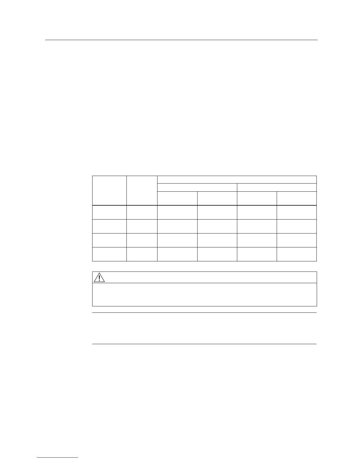
Table 4- 3 Using an output reactor or a sine-wave filter as specified in the catalog, the following
cable lengths are possible
Max. permissable motor cable length using …
… an output reactor with … … a sine-wave filter with …
Frame size HO power
rating
… screened
cables
… unscreened
cables
… screened
cables
… unscreened
cables
FSA 0.37 kW ...
1.5 kW
100 m
110 yd.
100 m
110 yd.
200 m
220 yd.
300 m
330 yd.
FSB … FSC 2.2 kW ...
11 kW
100 m
110 yd.
150 m
160 yd.
200 m
220 yd.
300 m
330 yd.
FSD … FSF 15 kW ...
110 kW
200 m
220 yd.
300 m
330 yd.
200 m
220 yd.
300 m
330 yd.
FSGX 132 kW ...
200 kW
300 m
330 yd.
450 m
490 yd.
300 m
330 yd.
450 m
490 yd.
CAUTION
The control cables must be laid separately from the power cables. The connection must be
carried out as shown in the installation section in this manual, to prevent inductive and
capacitive interference from affecting the correct function of the system.
Note
Ensure that the appropriate circuit-breakers or fuses with the specified current rating are
connected between the power supply and the inverter. The technical specifications contain
information about the circuit breaker and fuses. See
Technical specifications (Page 65).

 Loading...


