Accessories
7.3 Braking Resistor
Power Module PM240
116 Hardware Installation Manual, 07/2009, A5E00807525B AD
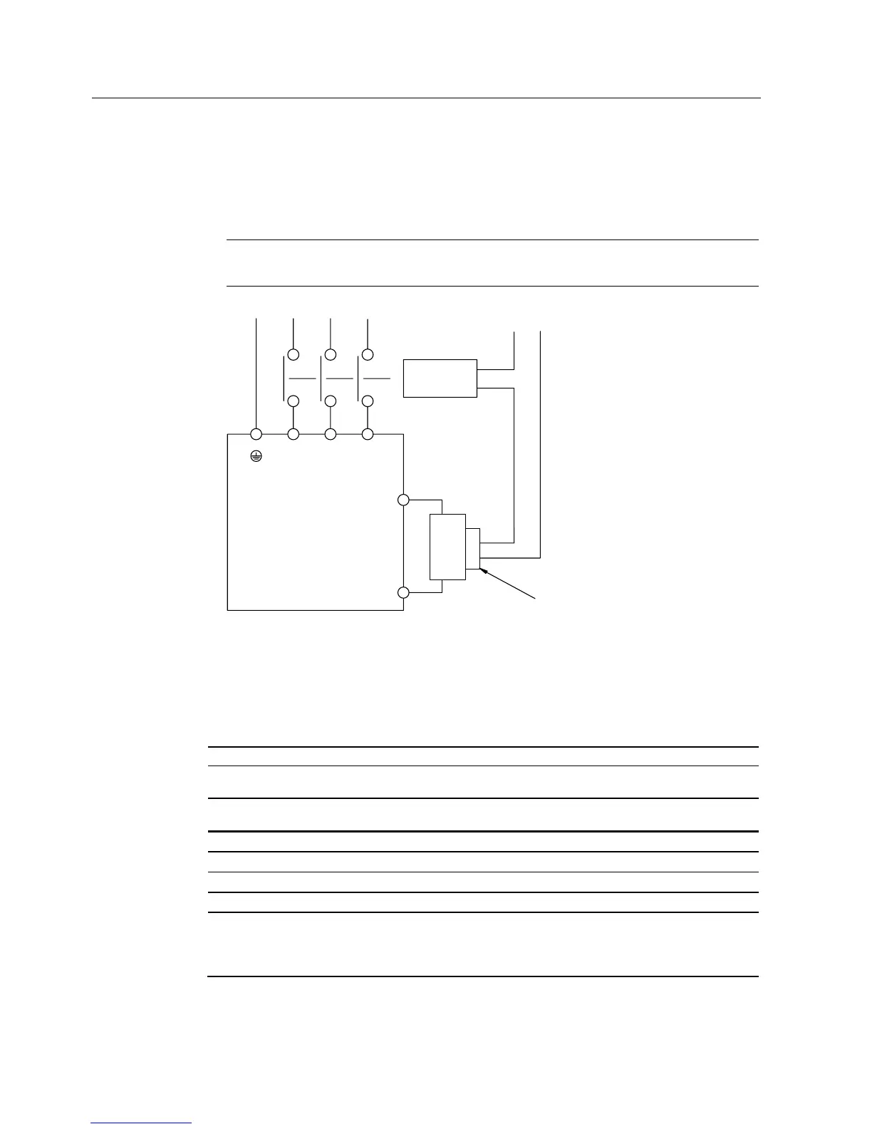
2. Establish the power supply to the Power Module through a contactor which then shuts
down the power supply when the resistor overheats. The thermostatic switch is
connected in series with the coil feeder cable for the main contactor. The contacts of the
thermostatic switch close again as soon as the resistor temperature has fallen below the
selected value.
Note
The contactor is not part of the braking resistor option.
&RQWDFWRU
3RZHU0RGXOH
8
/
8
/
8
/
3(
/
/
/
9'&
9$&
0D[
EUDNLQJ
UHVLVWRU
7
7
7HPSHUDWXUH
3URWHFWLYHFLUFXLWEUHDNHU
5
5
Figure 7-21 Protecting the braking resistor by a circuit breaker
7.3.4 Technical specifications of the braking resistor
Table 7- 26 Technical specifications, braking resistors, Part 1
Resistor for Power Module ... FSA FSB FSC FSD
Nominal power (HO) of the
Power Module
0.37 kW ...
1.5 kW
2.2 kW ... 4 kW 5.5 kW ...
11 kW
15 kW ... 22 kW
Order number 6SE6400-
4BD11-0AA0
6SE6400-
4BD12-0BA0
6SE6400-
4BD16-5CA0
6SE6400-
4BD21-2DA0
Resistance 390 Ω 160 Ω 56 Ω 27 Ω
Rated power P
DB
0.1 kW 0.2 kW 0.65 kW 1.2 kW
Peak power P
max
1.7 kW 4.0 kW 13 kW 24 kW
Degree of protection IP20 or IPXXB IP20 or IPXXB IP20 or IPXXB IP20 or IPXXB
Power Connections Cable 3 x
2.5 mm
2
shielded,
length 0.5 m
Cable 3 x
2.5 mm
2
shielded, length
0.5 m
Cable 3 x
2.5 mm
2
shielded, length
0.9 m
M6 studs

 Loading...


