Accessories
7.2 Brake chopper (FSGX)
Power Module PM240
Hardware Installation Manual, 07/2009, A5E00807525B AD
105
Connection overview
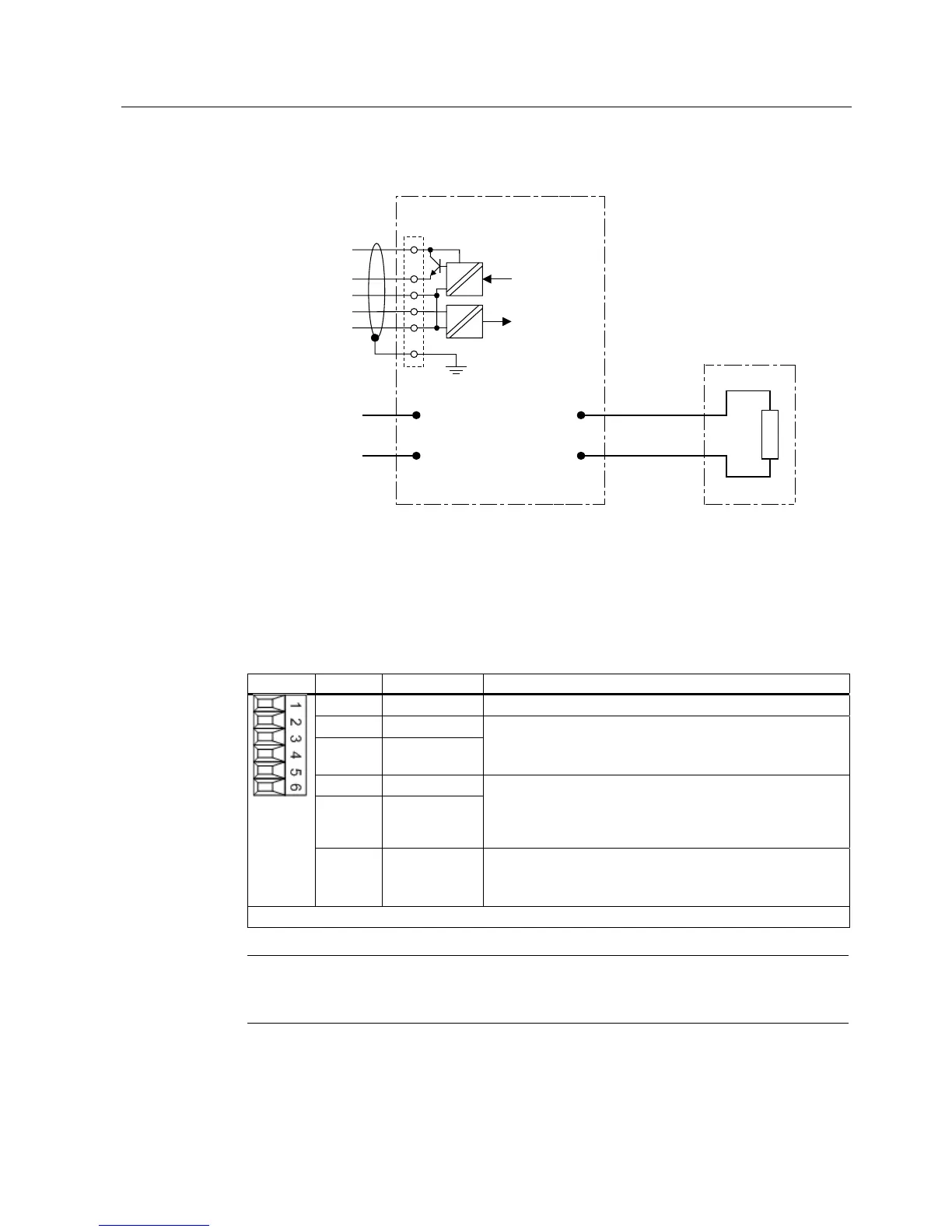
%UDNHFKRSSHU
%UDNLQJUHVLVWRU
&RQQHFWLQJWKH
EUDNLQJUHVLVWRU
&RQQHFWLRQDWWKH
'&OLQN
)DXOW
,QKLELW
)DXOWRXWSXW
,QKLELWLQSXW
'&3$
'&1$
5
5
9
9
9
Figure 7-13 Connection overview of the brake chopper
Digital input and output
The connection of the digital input and output is not required for the function of the brake
chopper.
Table 7- 21 Terminal block X21
Terminal Designation Technical specifications
1 Shield Shield connection for terminals 2 ... 6
2 0 V
3 Inhibit
(digital input)
High signal level: +15 V to 30 V
Current consumption: 2 mA to 15 mA
Low signal level: -3 V to 5 V
4 0 V
5 Fault
(digital output)
High signal: No fault
Low signal: Fault present
Voltage: 24 V DC
Load current: 0.5 mA to 0.6 mA
6 +24 V Voltage: +18 V to +30 V
Typical current consumption (induced current consumption):
10 mA at 24 V DC
Max. connectable cross-section 1.5 mm
2
Note
Applying a high signal to terminal X21.3 inhibits the brake chopper. With a falling edge,
pending fault codes are acknowledged.

 Loading...


