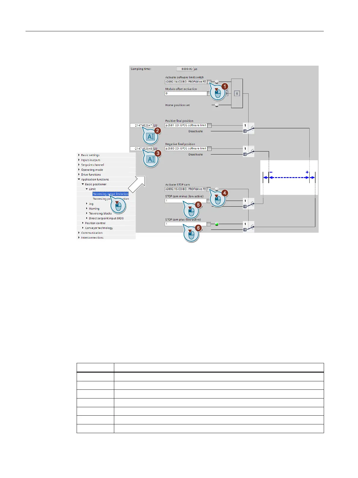
Procedure
1. Enable the software limit switch.
2. Move the axis to the positive end position in your machine. Set the position of the software
limit switches to the actual position value.
3. Move the axis to the negative end position in your machine. Set the position of the software
limit switches to the actual position value.
4. Enable the STOP cams.
5. Interconnect the signal of the STOP cam minus with the corresponding signal of your
machine.
Signal = 0 means an active STOP cam.
6. Interconnect the signal of the STOP cam plus with the corresponding signal of your machine.
You have now set the limits of the positioning range.
❒
Parameter Meaning
p2568 STOP cam activation
p2569 STOP cam, minus
p2570 STOP cam, plus
p2578 Software limit switch, minus signal source
p2579 Software limit switch, plus signal source
p2580 Software limit switch, minus
p2581 Software limit switch, plus
Commissioning
6.3 Limiting the positioning range
Basic positioner
44 Function Manual, 09/2020, FW V4.7 SP13, A5E34257659B AG

 Loading...


