4. Set the approach velocity to the reference point.
5. Set the approach velocity to the zero mark.
6. Specify the reference point coordinate.
7. Specify the reference point oset.
8. Specify the max. permissible distance to the reference cam in step 1 of active referencing.
9. If a reference cam is available: Dene the maximum permitted distance to the zero mark.
10.If no reference cam is available: Dene the tolerance for travel to the zero mark.
11.Close the screen form.
You have set the USB reference point approach.
❒
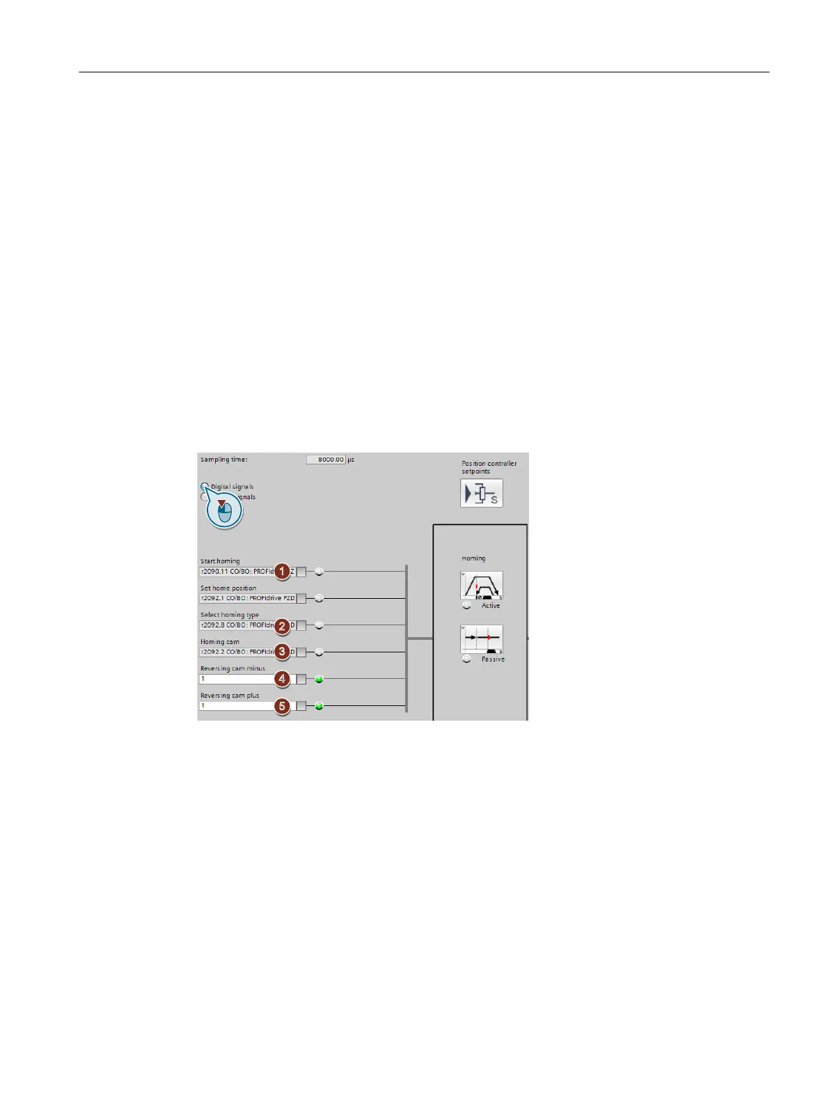
Dening the digital signals for controlling referencing
Procedure
1. This signal starts the reference point approach.
2. This signal must be 0 for the reference point approach.
3. Interconnect the signal of the reference cam with the corresponding signal of your machine.
4. If you use the reversing cam minus, interconnect the reversing cam with the corresponding
signal, e.g. with the eldbus.
0 = Reversing cams active.
5. If you use the reversing cam plus, interconnect the reversing cam with the corresponding
signal, e.g. with the eldbus.
0 = Reversing cams active.
You have now dened the digital signals for controlling.
❒
Commissioning
6.6 Referencing
Basic positioner
Function Manual, 09/2020, FW V4.7 SP13, A5E34257659B AG 61

 Loading...


