6DIHW\IXQFWLRQ
6DIHW\IXQFWLRQ
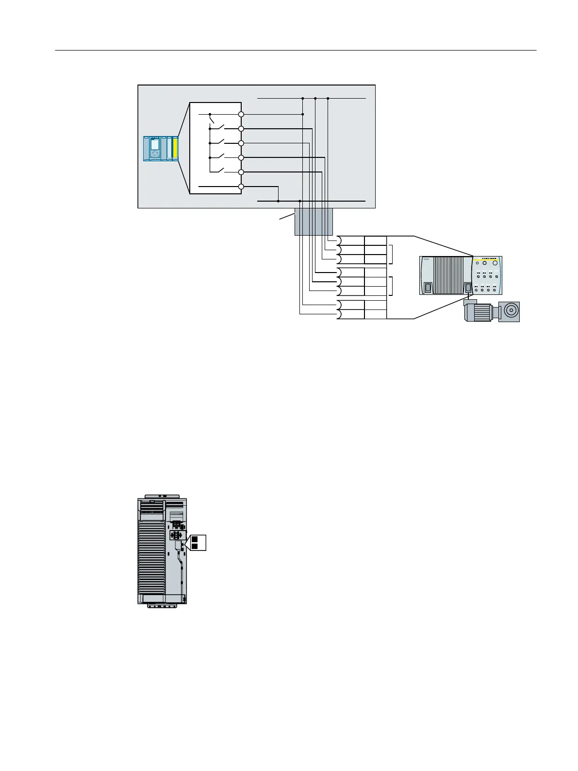
&DEOHZLULQJURXWHGLQVWHHOFRQGXLW
)',
)',
;',
;/
;',
;
',
;
/
;
',
;0
;/
6,1$0,&6
*'
9'&
0
)'4[9'&$330
6
SINAMICS G120D requires a PP-switching fail-safe output.
1)
The F-DQ module must be configured to be PP-switching.
2)
You may operate the inverter and the S7‑1500 with different 24‑V supplies - as well as with the
same 24‑V supply.
Figure 4-30 Connecting the S7‑1500 using a SINAMICS G120D as example
4.4.3 Wiring examples according to SIL 3 and PL e
Wiring examples for the STO function corresponding to PL e according to EN 13849-1 and
SIL 3 according to IEC 61508 are provided on the following pages.
Preconditions when using the STO safety function according to SIL 3:
● You are using a PM240‑2 or PM240P‑2, FSD … FSF Power Module
● You control the STO safety function using the terminals of the
PM240‑2 or PM240P‑2 Power Module.
● Both switches on the Power Module are in the “ON” position.
If, in an example, two or more terminals of the inverter are connected together, then you must
connect jumpers that are as short as possible directly at the terminals.
Installing
4.4 Controlling via a fail-safe digital input
Safety Integrated - SINAMICS G110M, G120, G120C, G120D and SIMATIC ET 200pro FC-2
Function Manual, 01/2017, FW V4.7 SP6, A5E34261271B AD 83

 Loading...


