4.6 Connecting a motor holding brake via Safe Brake Relay
The Brake Relay must be connected to the protective conductor if the motor holding brake is
supplied from a PELV circuit.
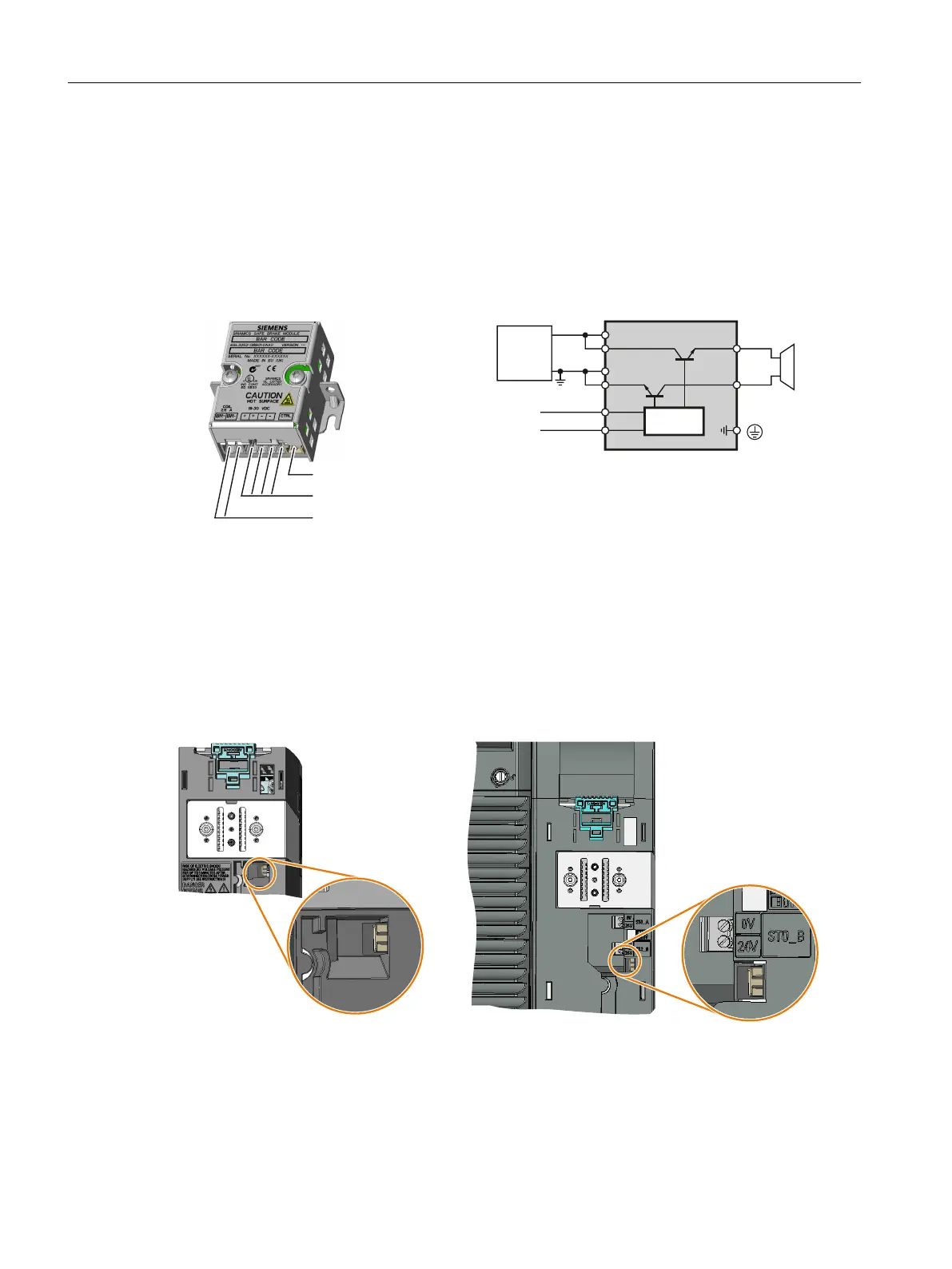
Safe Brake Relay - connection and circuit diagram
7RWKHPRWRUKROGLQJEUDNH
WRWKHLQYHUWHU
9H[WHUQDO
9'&
H[WHUQDO
%UD
NLQJ
FRLO
WRWKHLQYHUWHU
&RQQHFWLRQV
&LUFXLWGLDJUDP
%5
%5
&75/
0
0
4.6.1 Connecting a Brake Relay at the PM240-2 and at the PM240P-2 Power Modules
Connecting the Brake Relay to the inverter
The connector for the Brake Relay is located at the front of the Power Module. Lay the cable
harness for the Brake Relay in the cable routing.
%UDNHUHOD\FRQQHFWRUIRU)6')6)
3RZHU0RGXOHVZLWK672WHUPLQDOV
%UDNHUHOD\FRQQHFWRUIRU)6$)6&
3RZHU0RGXOHVZLWKRXW672WHUPLQDOV
Installing
4.6 Connecting a motor holding brake via Safe Brake Relay
Safety Integrated - SINAMICS G110M, G120, G120C, G120D and SIMATIC ET 200pro FC-2
98 Function Manual, 01/2017, FW V4.7 SP6, A5E34261271B AD

 Loading...


