4.6.2 Connecting a Brake Relay at a PM250 Power Module
Connecting the Brake Relay to the inverter
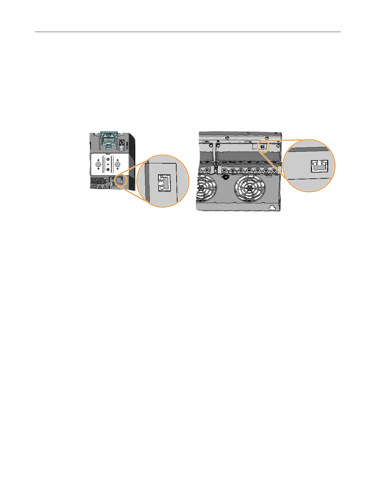
The connector for the brake relay is located at the front of the Power Module for the FSC frame
size. These Power Modules have a cable entry for the connecting cable to the Brake Relay.
The connector for the Brake Relay is located at the bottom of the Power Module for the FSD
… FSF frame sizes.
3RZHU0RGXOH)6&3RZHU0RGXOH)6')6)
Figure 4-52 Connector position for the Brake Relay
Installing
4.6 Connecting a motor holding brake via Safe Brake Relay
Safety Integrated - SINAMICS G110M, G120, G120C, G120D and SIMATIC ET 200pro FC-2
Function Manual, 01/2017, FW V4.7 SP6, A5E34261271B AD 99

 Loading...


