The two signals of the fail-safe digital output each have the same state:
● High signal or NO contact closed: The fail-safe digital output is active.
● Low signal or NO contact open: The fail-safe digital output is not active.
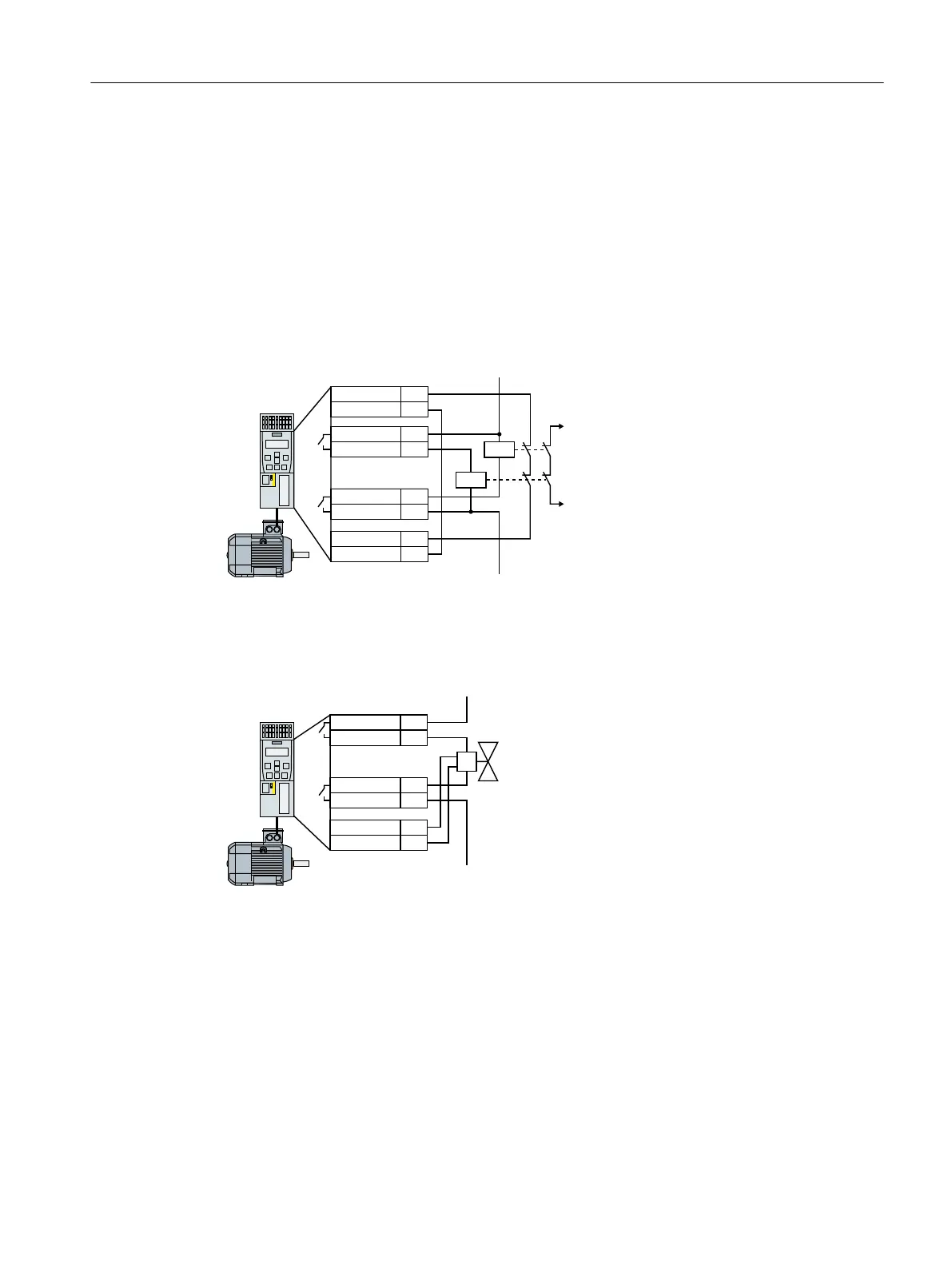
4.5.2 Connecting the fail-safe digital output for a SINAMICS G120
Connecting a relay
'212
',
',&20
'2&20
'212
'2&20
9RXW
8
H[W
0
H[W
*1'
Figure 4-45 Connecting a relay at the F-DO
Connecting an actuator with feedback signal
'212
',
',&20
'2&20
'212
'2&20
8
H[W
0
H[W
Figure 4-46 Connecting an F-DO to an actuator
Installing
4.5 Evaluating via a fail-safe digital output
Safety Integrated - SINAMICS G110M, G120, G120C, G120D and SIMATIC ET 200pro FC-2
Function Manual, 01/2017, FW V4.7 SP6, A5E34261271B AD 95

 Loading...


