Components in separate control cabinets
:LULQJLQVWHHOFRQGXLW
&RQWUROFDELQHW
&RQWUROFDELQHW
/RJLF
/RJLF
0
6WDUW
5.$$
444/0
7,1,1,1 ,17,1,1,1,1
5.$$
/044
7,1,17,1,1
9'&
0
672B$
672B%
9
9
9
9
6,1$0,&6*
3RZHU0RGXOH
30
303
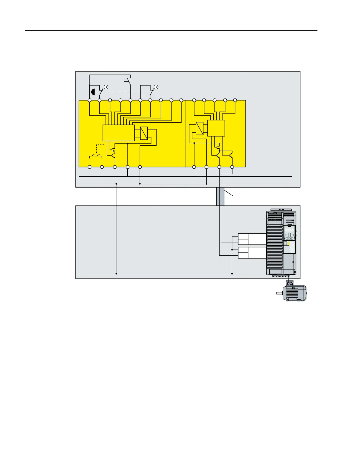
Figure 4-38 Wiring inverters and modular safety systems in separate control cabinets
When installed in separate control cabinets, route the cables between the modular safety
system and the inverter, protected against cross and short-circuits.
If you wish to use the fail-safe digital outputs of the 3RK3 central module for a two-channel
signal transfer, then you must adapt the discrepancy monitoring of the inverter to the different
switching times of electronic output and relay contact.
Installing
4.4 Controlling via a fail-safe digital input
Safety Integrated - SINAMICS G110M, G120, G120C, G120D and SIMATIC ET 200pro FC-2
90 Function Manual, 01/2017, FW V4.7 SP6, A5E34261271B AD

 Loading...


