V/f control
Function diagrams
2-585
© Siemens AG 2011 All Rights Reserved
SINAMICS G120 / Control Units CU240B/E-2 Parameter Manual (LH11), 01/2011
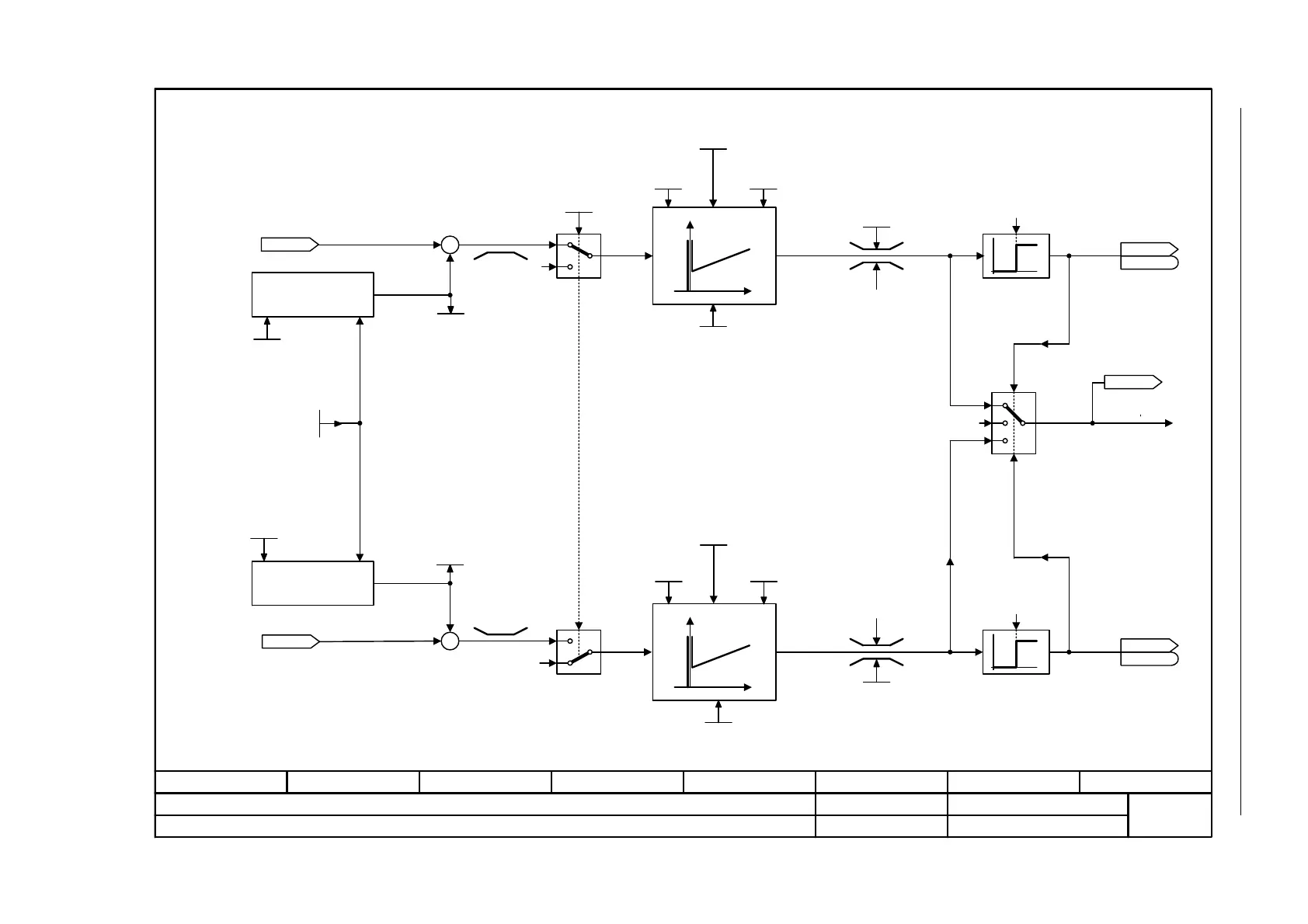
Fig. 2-82 6320 – Vdc_max controller and Vdc_min controller (PM230 / PM240)
- 6320 -
Function diagram
87654321
FP_6320_97_02.vsd
V/f control
G120 CU240B/E-2
13.12.2010 V4.4
Vdc_max controller and Vdc_min controller (PM230 / PM240)
0
1
1,3
0,2
+
0
1
+
0
0
0
2,3
0,1
[2526.2]
[2526.2]
0
0
0
0
Calculate on_level
r0070
Vdc act val [V]
Vdc_max on_level [V]
r1282
Vdc_max SenseOnLev
0 ... 1
p1294 (0)
V_connect
1 ... 63000 [V]
p0210 (400)
Vdc_min on_level
65 ... 150 [%]
p1285 [D] (76)
Vdc_min on_level [V]
r1286
r0070
Vdc act val [V]
Vdc_ctrl Kp
0.00 ... 100.00
p1290 [D] (1.00)
Vdc_ctrl t_rate
0 ... 1000 [ms]
p1292 [D] (10)
Vdc_ctrl Tn
0 ... 10000 [ms]
p1291 [D] (40)
Vdc_ctrl Kp
0.00 ... 100.00
p1290 [D] (1.00)
Vdc_ctrl t_rate
0 ... 1000 [ms]
p1292 [D] (10)
Vdc_ctrl Tn
0 ... 10000 [ms]
p1291 [D] (40)
Vdc_max dyn_factor
1 ... 10000 [%]
p1283 [D] (100)
Vdc_min dyn_factor
1 ... 10000 [%]
p1287 [D] (100)
r1298
Vdc_ctrl output [1/min]
ZSW cl-loop ctrl
r0056
r0056
.14
ZSW cl-loop ctrl
r0056
r0056
.15
Calculate on_level
<1> p1280
<1>
0: Inhib Vdc ctrl
1: Enable Vdc_max controller
2: Enable Vdc_min controller (kinetic buffering) (only for PM240)
3: Enable Vdc_min controller and Vdc_max controller (only for PM240)
[1690]
0
0
Vdc_min outp_lim
0.00 ... 600.00 [Hz]
p1293 [D] (600.00)
Vdc_min outp_lim
0.00 ... 600.00 [Hz]
p1293 [D] (600.00)
<2>
Value range and/or factory setting depend on Power Module
<2>
Vdc_ctr config U/f
0 ... 3
p1280 [D] (1)
Vdc_max (V/f control)
Vdc_min (V/f control)
(only for PM240)

 Loading...


