Connection
3.4 Installing the Control Unit
CU240S and CU240E Control Units, FW 3.2
42 Operating Instructions, 03/2009, A5E02440075B AA
3.4.1 Interfaces, connectors, switches, control terminals, LEDs on the CU
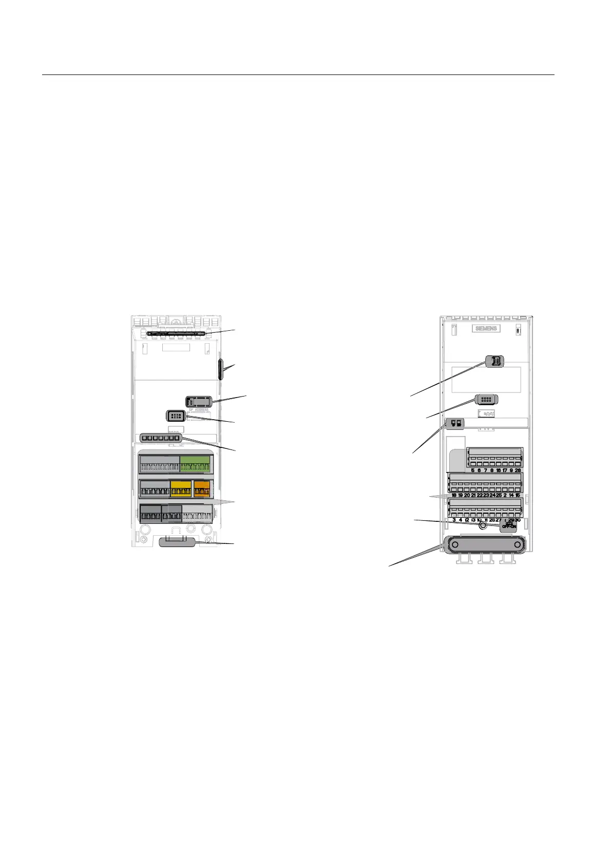
Overview of the process and user interfaces
The following interfaces are provided on the Control Unit
● Terminals for the input and output signals
● Card slot to upload and download inverter settings
● Connector to communicate with higher-level controls
● DIP switches to configure the speed encoder, the analog inputs and, if required, to set the
PROFIBUS address.
● LEDs for diagnostics
All of the these interfaces are shown in the following diagram.
&86
&8(
00&FDUGVORW
',3VZLWFKHVIRUFRQILJXULQJWKH
DQDORJLQSXWVDQGHQFRGHU
',3VZLWFKHVIRUVHWWLQJWKH352),%86DGGUHVV
RQWKHVLGHRIWKH&8RQO\IRU'3YHUVLRQV
/('IRUWKHLQYHUWHUVWDWXVGLVSOD\
,QWHUIDFHIRU%233&FRQQHFWLRQNLW
7HUPLQDOVIRUGLJLWDORUDQDORJLQSXWDQG
RXWSXWVLJQDOV
&RPPXQLFDWLRQLQWHUIDFHWRDKLJKHUOHYHOFRQWURODV
68%'RU5-FRQQHFWRU
',3VZLWFKIRUEXVWHUPLQDWLQJUHVLVWRU
6KLHOGSODWH
Figure 3-3 User interfaces of the CU240E/S
 Loading...