EasyManuals Logo
Home>Siemens>Computer Hardware>DP/AS-Interface Link 20E

Siemens DP/AS-Interface Link 20E User Manual

Siemens DP/AS-Interface Link 20E
160 pages
To Next Page IconTo Next Page
To Previous Page IconTo Previous Page
Page #80 background imageLoading...
Page #80 background image
Using the Command Interface
80
DP/AS-Interface Link 20E
Release 11/2002
C79000-G8976-C138–04
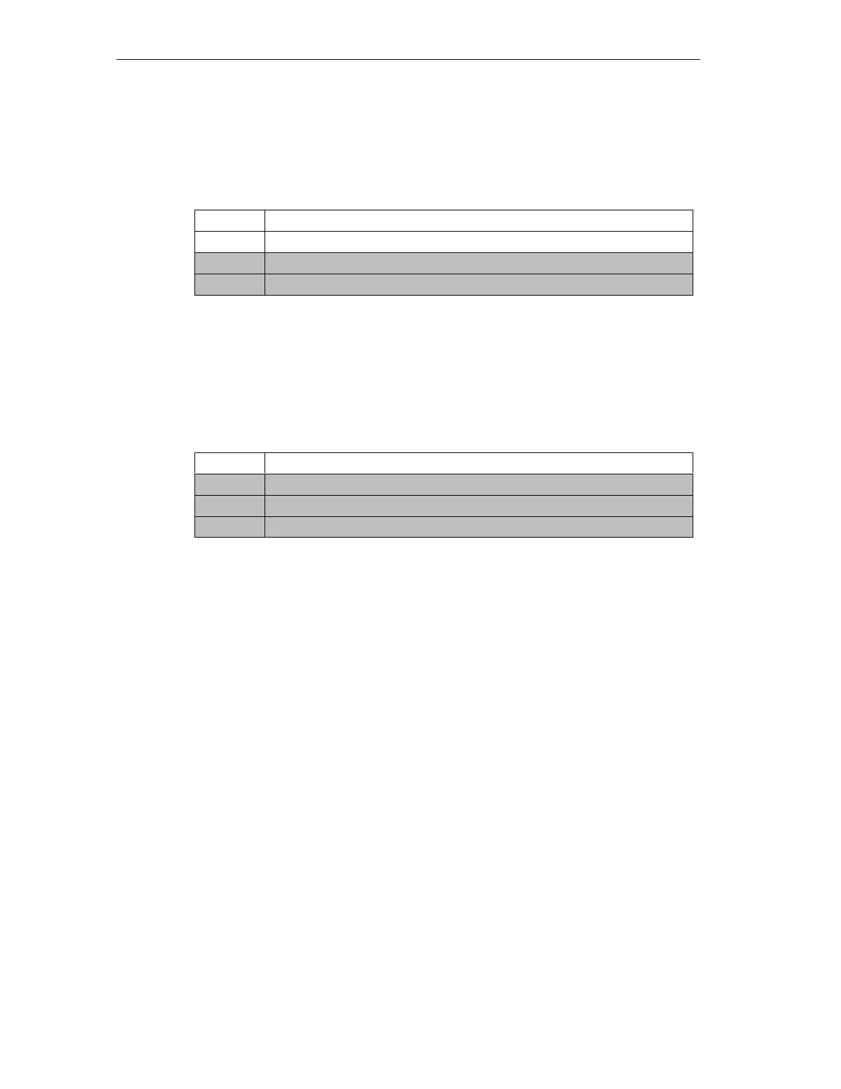
General Structure of the Send Buffer
The basic structure of the send buffer for commands is shown below. The bytes
only relevant with certain commands are shown on a gray background.
Byte Meaning
q+0 Command number
q+1 Job data
q+... Job data
q = start address of the send buffer on the DP master
General Structure of the Receive Buffer
The basic structure of the response buffer is shown below. The bytes only relevant
with certain commands are shown on a gray background.
Byte Meaning
n+0 Response data
n+1 Response data
n+... Response data
n = start address of the response buffer on the DP master

Table of Contents

Questions and Answers:

Question and Answer IconNeed help?

Do you have a question about the Siemens DP/AS-Interface Link 20E and is the answer not in the manual?

Siemens DP/AS-Interface Link 20E Specifications

General IconGeneral
BrandSiemens
ModelDP/AS-Interface Link 20E
CategoryComputer Hardware
LanguageEnglish

Related product manuals