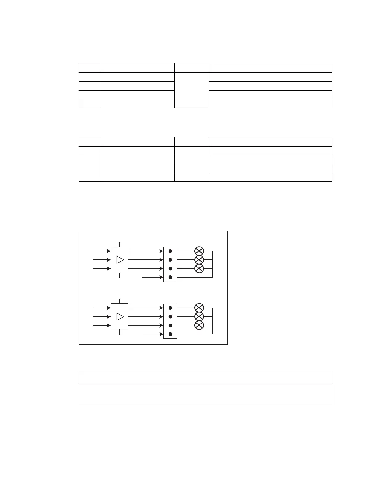
Rotary switch: Feed override X30
Connector designation: X30
Connector type: 2 x 5-pin plug connector, according to EN 60603-13 with coding
Max. cable length: 0.6 m
Table 1-15 Assignment of X30 connector (on delivery)
Pin Name Type Meaning
1 N.C. - Not connected
2 N.C. - Not connected
3 M V Ground
4 N.C. - Not connected
5 P5 V 5 V supply
6 OV_VS16
I
Override rotary switch value 16
7 OV_VS8 Override rotary switch value 8
8 OV_VS4 Override rotary switch value 4
9 OV_VS2 Override rotary switch value 2
10 OV_VS1 Override rotary switch value 1
Rotary switch: Spindle override X31
Connector designation: X31
Connector type: 2 x 5-pin plug connector, according to EN 60603-13 with coding
Max. cable length: 0.6 m
Table 1-16 Assignment of X31 connector (on delivery)
Pin Name Type Meaning
1 N.C. - Not connected
2 N.C. - Not connected
3 M V Ground
4 N.C. - Not connected
5 P5 V 5 V supply
6 OV_SP16
I
Override rotary switch value 16
7 OV_SP8 Override rotary switch value 8
8 OV_SP4 Override rotary switch value 4
9 OV_SP2 Override rotary switch value 2
10 OV_SP1 Override rotary switch value 1
General information and networking
1.3 Connecting
Handheld Terminal HT 8
32 Manual, 07/2015, A5E36371621B-AB