Operating panel
6
Building Technologies 009929_a_en_--.doc
Fire Safety & Security Products 11.2006
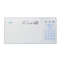
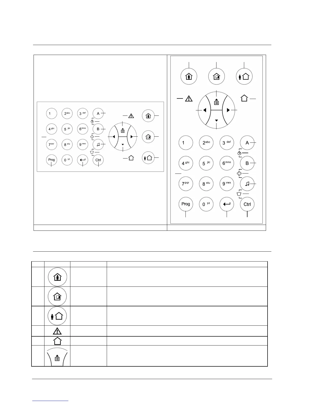
2 Operating panel
2.1 Operating panel layouts
1
2
3
8
10
11
12
13
14
15
16
17
18
19
5
4
6
9
7
5
11
12
13
14
15
16
4
10
1 2 3
6
9
17 18
7
8
19
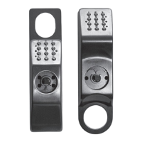
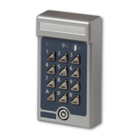
Vertical control unit or external keypad Horizontal control unit
Tab. 1 Keypad layouts
2.2 Description of the Operating panel keys and indicators
No. Symbol Key/Indicator. Description
1
<STAY>
Internal system activated
Button: Arm in Stay mode
LED: Stay arming mode activated
2
<BYPASS>
Bypass key
Button: Bypass Zones
LED: Zone bypass indication
3
<ARM>
Arming
Button: Arm in Full Set Mode
LED: Full Set arming mode activated
4
<TROUBLE>
Trouble indicator (red)
Trouble indication
5
<OK>
System OK (ARM) indicator (green).
6
<UP>
arrow
Menu up or reading out messages
(Event Log)