LMV Series Technical Instructions
Document No. LV5-10
00
SCC Inc. Page 3 Section 1
Control Panel Components (continued)
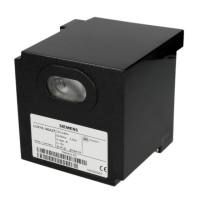
Display – Qty (1) Required
Each LMV5 must be equipped wit
h one AZL52.40B1 display. See page 25 for mounting
information and panel cutout dimensions.
AZL52.40B1
Display with Modbus port, PC
port, backlight, six
languages available
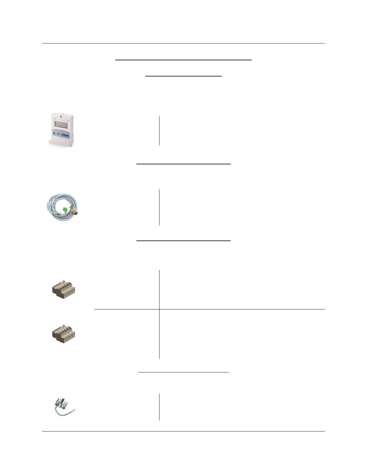
Display Cable – Qty (1) Required
Each LMV5 must be equipped wit
h a cable to connect the AZL52 display to the LMV5.
AGG5.635
Pre-made 9 foot cable for conn
ecting the AZL52
display to the LMV5
Base Plug Set – Qty (1) Required
The terminal plug sets for the LMV5 are s
old separately. Each LMV5 needs one base plug set.
Additional plug sets are available (see “Control Panel Spare Parts”).
AGG5.720
Plug set containing all terminals for a typical LMV5
system. Will accommodate a system with O
2
trim,
three actuators, one transformer, and no fuel meters
AGG5.7COMPLETE
Plug set containing all te
rminals necessary for a
maximum LMV5 system. Will accommodate a
system with a VFD, O
2
trim, six actuators, two
transformers, and two fuel meters
Strain Relief – Qty (1) Required
A strain relief is required to ground the CANbus shield to th
e LMV5.
AGG5.110
Strain relief and actuator CANbus grounding
 Loading...