LMV Series
Technical Instructions
LV5-1000
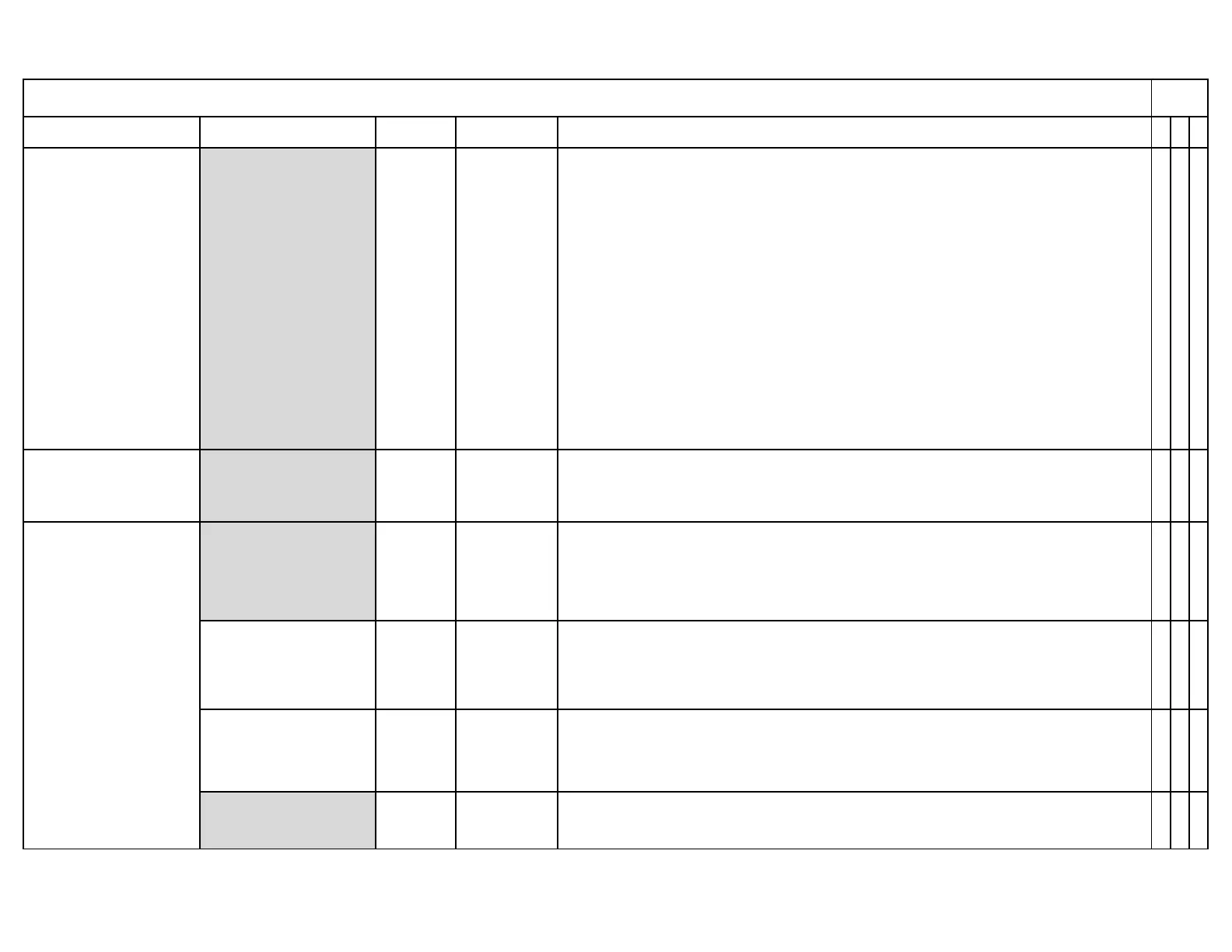
Menu Path Parameter Default Range Description
51.1
52.2
52.4
LEGEND - Password Access: (U)=User, (S)=Service, (O)=OEM, Shaded = Commonly Used, ** = Must Set, X = Has Function, / = Partial Function
LMV
Params & Display>
O2Contr/Alarm>
Gas/Oil Settings
OptgMode (S) man deact
man deact
O2 Limiter
O2 Control
conAutoDeac
Four settings are available for each fuel:
1) man deact - O2 trim controller AND O2 monitor are de-activated. Burner will run on ratio
control curve.
2) O2 Limiter - Only the O2 Alarm is activated. Any O2 fault, including low O2 levels in the
stack, will cause a burner lockout. O2 Alarm curve must be input for this function.
3) O2 Control - O2 trim controller and O2 Alarm are activated. Any O2 fault will cause a
burner shutdown. O2 Alarm curve and O2 setpoint curve must be input for this function.
4) ConAutoDeac - configured to automatically deactivate the O2 trim controller if any O2
fault occurs. Burner runs on ratio curve when O2 control auto deactivates.
NOTE: "auto deact" will appear when the O2 control deactivates itself, due to an operating
fault or component malfunction. If the control goes into auto deact, choose O2 Limiter, O2
Control, or ConAutoDeac to re-activate. This can also be reactivated under: Operation >
O2Ctrl activate .
x x
Params & Display>
O2Contr/Alarm>
Gas/Oil Settings
O2 Control (S) Not Set Points 2-15
This is where the O2 ratio control and the O2 control curves are input. An O2 ratio contol
point and O2 control point must be set for every point on the position control curve except
for point 1. See Section 6 for more detail.
x x
O2 Alarm (S) Not Set Points 1-15
This is where the low O2 alarm curve is input. A low O2 alarm point must be set for every
point on the position control curve. The position control curves (fuel air ratio curves) must be
set before this curve is entered. Points can be set by typing in an O2 value or by probing each
point. See Section 6 for more detail.
x x
Time O2 Alarm (O) 3s 1-60s
The maximum amount of time the measured %O2 is permitted to be higher than O2
MaxValue or lower than the O2 Alarm . Essentially a timer to give the LMV5 time to correct
an O2 excursion. Set to the highest value that is safe for the application.
x x
Type O2 MaxValue (O)
O2Max
Value
O2MaxValue
O2MaxCurve
Either the O2 ratio control curve (O2MaxCurve) or a single value (defined by O2MaxValue )
can be used to define the maximum allowable %O2 for a given burner. If set to
"O2MaxValue", the value (defined below) is used for all firing rates.
x
O2 MaxValue (S) 15% 0-15%
Sets the maximum allowable %O2 for a given burner if parameter Type O2 MaxValue (see
above) is set to "O2MaxValue".
x x
Params & Display>
O2Contr/Alarm>
Gas/Oil Settings>
O2 Alarm
SCC Inc. Page 22 Section 3
 Loading...