A Appendix A - Contact Information.............................................................................................................109
A.1 Product Information Availability............................................................................................109
A.2 Contacts...............................................................................................................................110
Tables
Table 4-1 Digital Output Solenoid Valve Groups.........................................................................................29
Table 4-2 SVCM I/O Assignments...............................................................................................................29
Table 4-3 SVCM Fault Indicators................................................................................................................29
Table 4-4 SVCM Specifications...................................................................................................................30
Table 4-5 Configuration...............................................................................................................................44
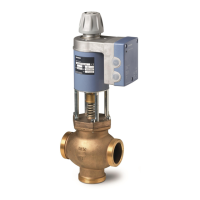
Table 4-6 Siemens Liquid Injection Valve...................................................................................................45
Table 4-7 Liquid sample inlet conditions.....................................................................................................45
Table 4-8 Configuration...............................................................................................................................53
Table 4-9 Performance and Requirements.................................................................................................53
Table 4-10 Dimensions..................................................................................................................................54
Figures
Figure 1-1 Pressure Switch and Purge Control Module.................................................................................8
Figure 1-2 Timing Coil for Pressure Switch....................................................................................................9
Figure 1-3 Airbath Oven Heater Control Loop..............................................................................................10
Figure 1-4 Programmed Temperature Airbath Oven (with Deflector)...........................................................11
Figure 1-5 Programmed Temperature Airbath Oven Component Locations................................................12
Figure 1-6 Airless Oven................................................................................................................................13
Figure 1-7 Location of Temperature Probes and Heaters in Airless Oven...................................................14
Figure 1-8 Airless Oven Heater Control Loop...............................................................................................14
Figure 1-9 Airless Oven Heater Locations....................................................................................................17
Figure 1-10 Typical Modular Oven Configuration...........................................................................................18
Figure 1-11 Heater and RTD Tubes for the Modular Oven............................................................................19
Figure 2-1 Valco Fitting.................................................................................................................................21
Figure 2-2 Siemens and Valco Fittings Compared.......................................................................................22
Figure 2-3 Siemens Fittings Assembly.........................................................................................................22
Figure 3-1 Temperature Control Module Connections.................................................................................23
Figure 4-1 Solenoid Valve Control Module (SVCM).....................................................................................27
Figure 4-2 Solenoid Control Module.............................................................................................................28
Figure 4-3 SLIV Installation Details..............................................................................................................33
Figure 4-4 SLIV Heater and Probe Connections in the Electronics Cabinet................................................34
Figure 4-5 Vaporization Temperature...........................................................................................................36
Table of contents
Maxum II Valves and Oven Components
Service Manual, 10/2018, A5E42019844001 5
 Loading...