4.4.2.6 M20 Procedure - Figures
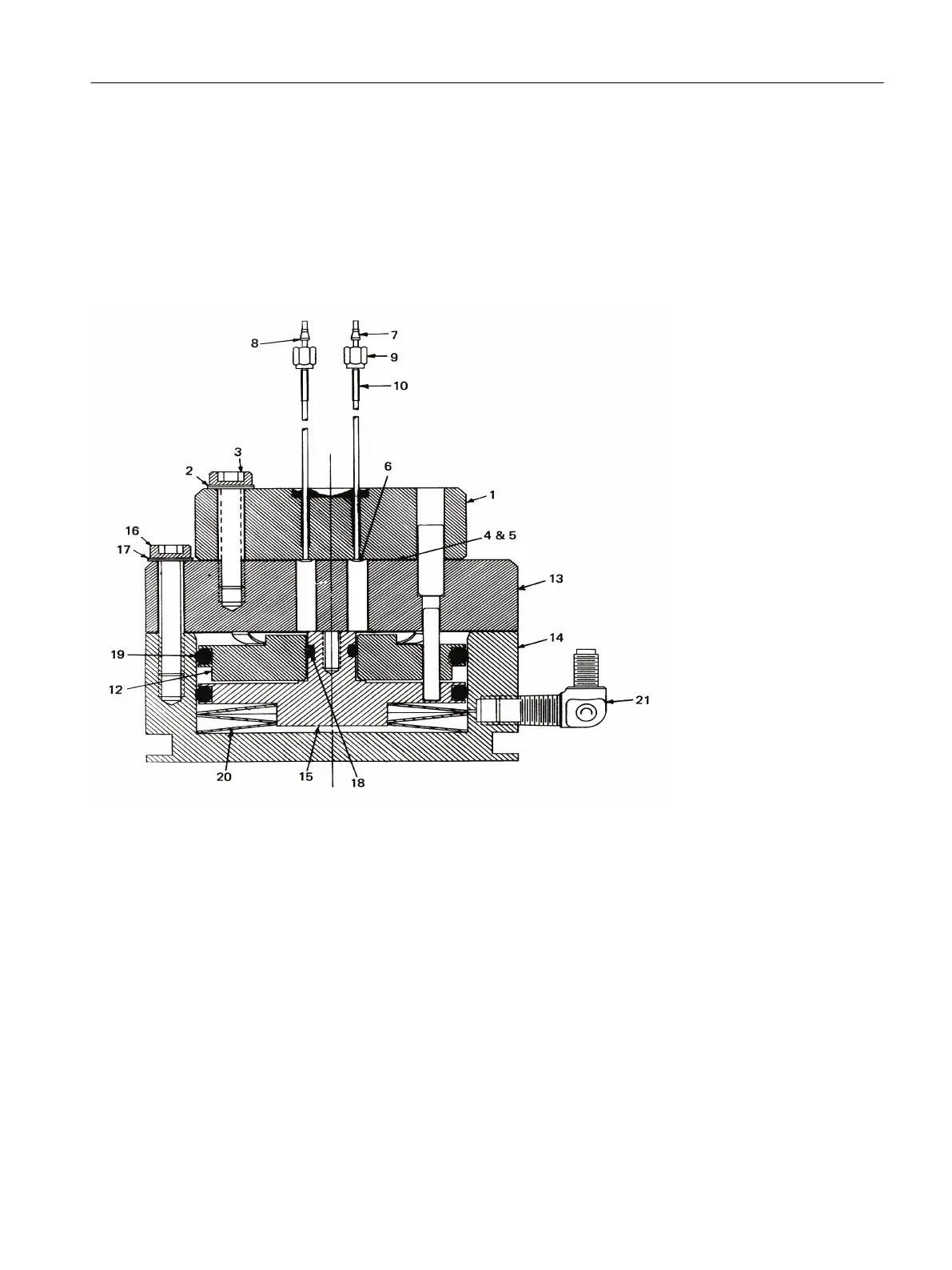
The following figures are intended for use as a reference throughout the procedure. The
numbers in the diagrams relating to individual components are referenced in parentheses in
the procedure steps.
1. Valve Cap
2. Allen Screws (3 total)
3. Belleville Washers (6 total)
4. Teflon Disc Seal Diaphragm
5. Dacron Cushion Diaphragm
6. Plungers (6 total)
7. Ferrule Top
8. Ferrule Bottom
9. Connector
10. Port Tubing
12. Air Loaded (Upper) Piston
13. Valve Plunger Body
14. Cylinder Base
15. Spring Loaded (Lower) Piston
16. Allen Screws (3 total)
17. Belleville Washers (6 total)
18. Inner (small) O-Ring
19. Outer (large) O-Rings
20. Large Belleville Washers (3 total)
Figure 4-15 Section View of Model 20 Valve
Valves
4.4 Model 20 Valve
Maxum II Valves and Oven Components
Service Manual, 10/2018, A5E42019844001 61

 Loading...