4.6.7 M11 Procedure - Figures
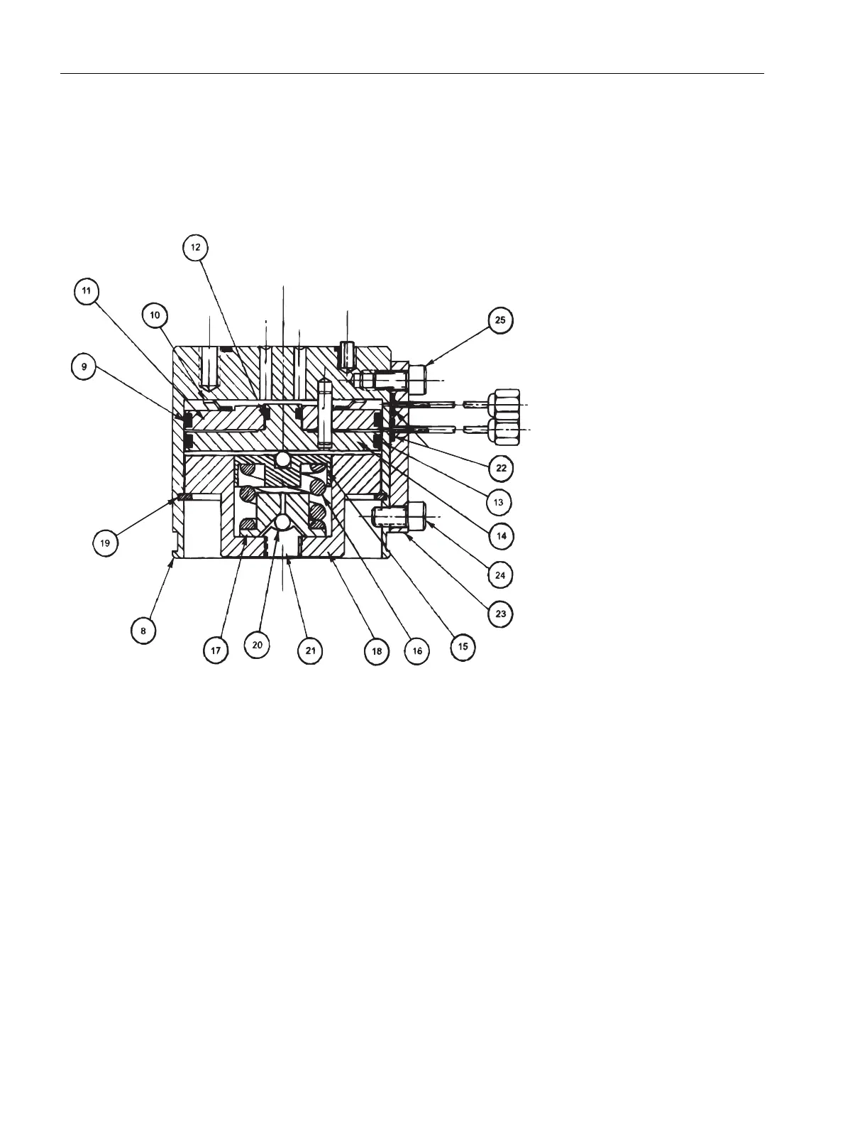
The following figures are intended for use as a reference throughout the procedure. The
numbers in the diagrams relating to individual components are referenced in parentheses in
the procedure steps.
8. Valve Body
9. O-Ring
10. Finger Spring of Air
Loaded Piston
11. Air Loaded Piston
12. O-Ring
13. O-Ring
14. Spring Loaded Piston
15. Compensation Plate
16. Compression Spring
17. Compression Plate
18. Retaining Base
19. Retaining Ring Clip
20. Ball 5/32”
21. Set Screw
22. O-Rings (3 total)
23. Air Signal Manifold
24. Screw 3/8”
25. Screw 1/2”
Figure 4-27 Model 11 (or Model 11 LDV) Valve without Valve Cap
Valves
4.6 Model 11 Valve
Maxum II Valves and Oven Components
88 Service Manual, 10/2018, A5E42019844001

 Loading...