5
08/2005 ShopTurn Functions
5.3 Turnin
5
♥ Siemens AG, 2005. All rights reserved
SINUMERIK 840D sl Operation/Programming ShopTurn (BAT) – 08/2005 Edition 5-199
Parameters Description Unit
T, D, F, S, V See Sec. "Creating program blocks".
Machining
type
Roughing
Finishing
+ Complete machining
Position Groove position:
Reference
point
Reference point:
X0
Reference point ¬ (abs)
mm
Z0 Reference point (abs) mm
B1 Recess width, bottom (incr.) mm
B2 Recess width, top (inc) alternative to B1 – (only for recess with oblique lines and
radii)
mm
T1 Recess depth at reference point (abs or inc) mm
T2 Recess depth opposite reference point (abs or inc) alternative to T1 –
(only for inclined recess with oblique lines, radii and chamfers)
mm
α0
Angle of the incline on which the recess should be machined – (only for inclined
recess with oblique lines, radii and chamfers)
The angles can be between -180 and +180°
Longitudinal recess: α
0
= 0° ⇒ Parallel to the Z axis
Face recess: α
0
= 0° ⇒ Parallel to the X axis
A positive angle indicates rotation from the X axis to the Z axis
Degrees
α1, α2
Flank angle (not for simple recess cycle)
Asymmetrical recesses can be described by separate flank angles. The angles can
be between 0 and < 90°.
Degrees
FS Chamfer (n = 1 ... 4) alternative to R (not for simple recess cycle) mm
R Radius (n = 1 ... 4) alternative to FS (not for simple recess cycle) mm
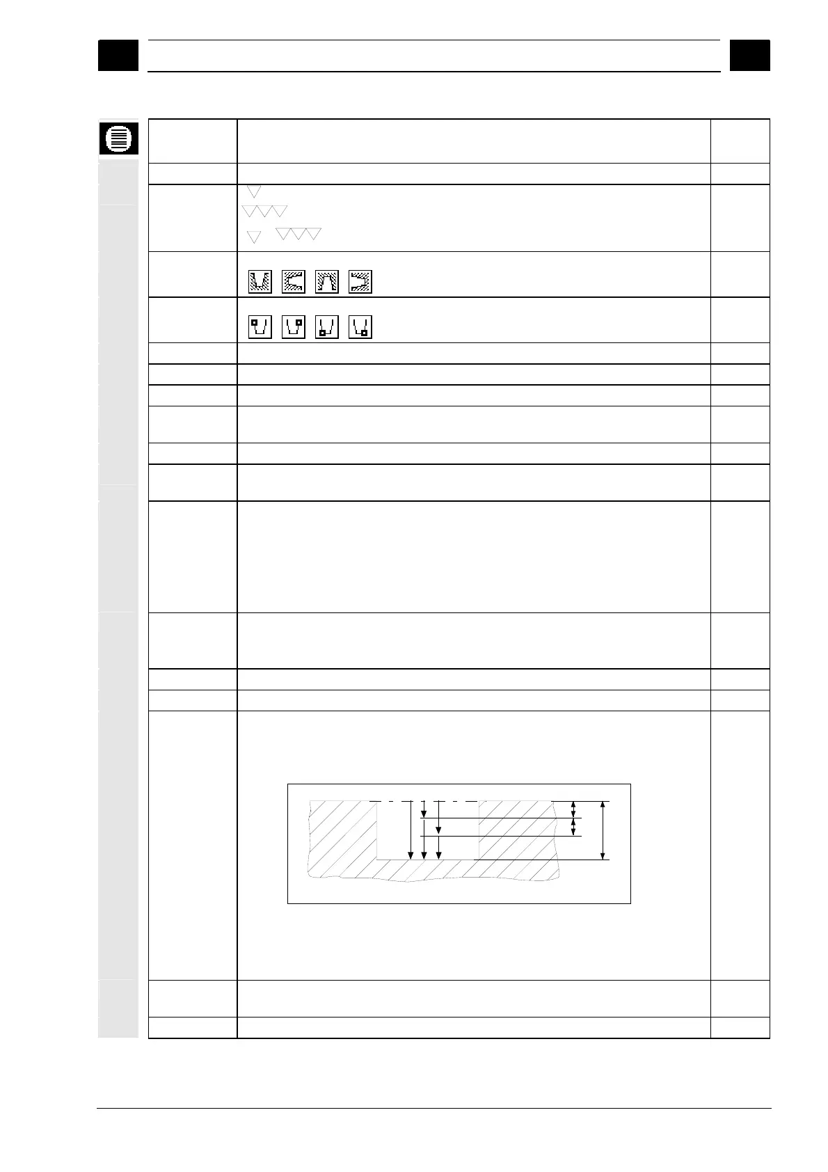
D Infeed depth for 1st cut (inc) – (for roughing only)
D=0: 1. 1st cut is made directly to final depth T1
D>0: The 1st and 2nd cuts are made alternately to infeed depth D
for improved chip clearance and avoidance of tool breakage.
12
3
4
5
D
T1
D
All further cuts are made directly to final depth T1.
The lateral infeed for the alternate cuts is determined automatically in the cycle.
Alternate cutting is not possible if the tool can only reach the recess base at one
position.
mm
U Contour-parallel finishing allowance in X and Z direction (inc) – (roughing only) –
(alternative to UX and UZ)
mm
UX Finishing allowance in X direction (inc) – (roughing only) – (alternative to U) mm
 Loading...


