5
08/2005 ShopTurn Functions
5.6 Contour millin
5
♥ Siemens AG, 2005. All rights reserved
SINUMERIK 840D sl Operation/Programming ShopTurn (BAT) – 08/2005 Edition 5-299
C0
X0
X1
DYZ
UYZ
UX
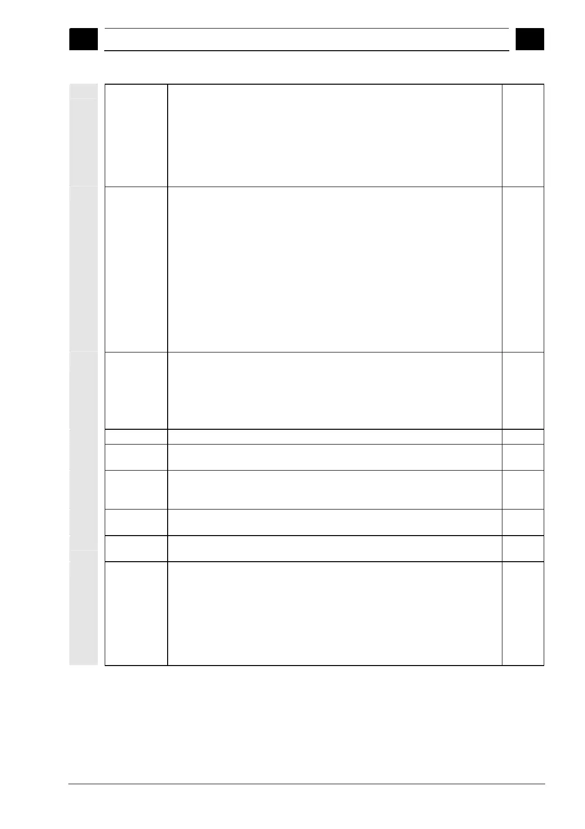
Peripheral surface Y:
Reference point
Reference point in X direction (abs.)
Depth with reference to X0 (abs. or inc.)
Maximum infeed in the YZ plane
Plane infeed in %: Ratio of plane infeed (mm) to milling cutter diameter (mm)
Finishing allowance in plane
Finishing allowance in depth
Degrees
mm
mm
mm
%
mm
mm
Starting point
X
Y
Y
Z
Determine start point automatically or enter it manually
Manual entry allows for a start point outside the pocket, whereby straight line
machining into the pocket is performed first, e.g. for a pocket with a side opening
without any insertion.
Start point X (abs.) – (only for end face/end face C and end face Y with manual start
point)
Start point Y (abs.) – (only for end face/end face C and end face Y with manual start
point)
Start point Y (abs.) – (only for peripheral face/peripheral face C and peripheral face
Y with manual start point)
Start point Z (abs.) – (only for peripheral face/peripheral face C and peripheral face
Y with manual start point)
mm
mm
mm
mm
Insertion Insertion strategy:
Oscillation: Oscillating insertion with the programmed angle (EW).
Helical: Helical insertion with the programmed radius (ER) and the programmed
gradient (EP).
Center: For this insertion strategy, a milling cutter is required that cuts in the center.
It is inserted at the programmed feedrate (FZ or FX).
EW Insertion angle (for oscillation only) Degrees
EP Maximum Insertion gradient (only for helical)
The gradient of the helix may be smaller in some geometric conditions.
mm/rev
ER Insertion radius (only for helical)
The radius must not be larger than the cutter radius, otherwise material will remain.
Also make sure the pocket is not violated.
mm
FZ Depth infeed feedrate (for end face/end face C and end face Y with central insertion
only)
mm/tooth
mm/min
FX Depth infeed feedrate (for peripheral surface/peripheral surface C and peripheral
surface Y with central insertion only)
mm/tooth
mm/min
Retraction
mode
If more than one insertion point is necessary, specify the retraction height to which
the tool retracts between insertion points:
To retraction plane
Z0+safety clearance (for end face/end face C and end face Y only) or
X0+safety clearance (for peripheral surface/peripheral surface C and peripheral
surface Y only)
If there are no islands larger than Z0 (X0) in the pocket area, Z0 + safety clearance
(X0 + safety clearance) can be programmed as the retraction mode.
 Loading...


