Prepping for Installation
Connecting a Communication Cable
22
Building Technologies 125-202
06/06/2017
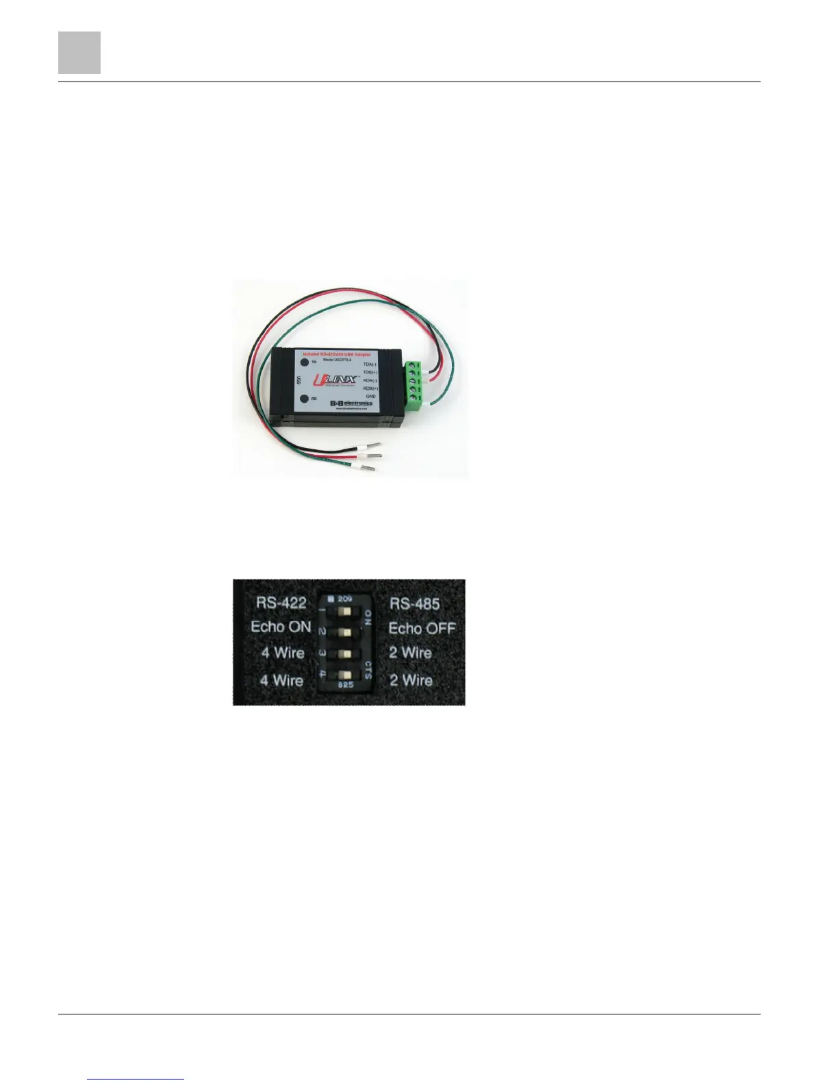
Connecting the Adapter to the Meter
To complete the connection between the MD Model Power Meter and the computer,
the three wires coming from the RS-485 adapter are plugged into the meter.
● Insert each white ferrule into the appropriate slots on the connector:
● The red wire inserts in (+)
● The black wire to (-)
● The green wire in GND
Figure 2: RS_485-Adapter
● Verify that the DIP switches on the back of the RS-485 Adapter are set to RS-485,
Echo Off, 2 Wire, 2 Wire as shown below before plugging into the adapter into the
MD-BMS and MD-BMED.
Figure 3: DIP Switches on Back of RS-485 Adapter
The adapter is ready to be connected to the MD-BMS or MD-BMED Power Meter.