Installation
50
Building Technologies 125-202
06/06/2017
4. Repeat Steps 1 through 3 if you are using more than one Rogowski Coil CT.
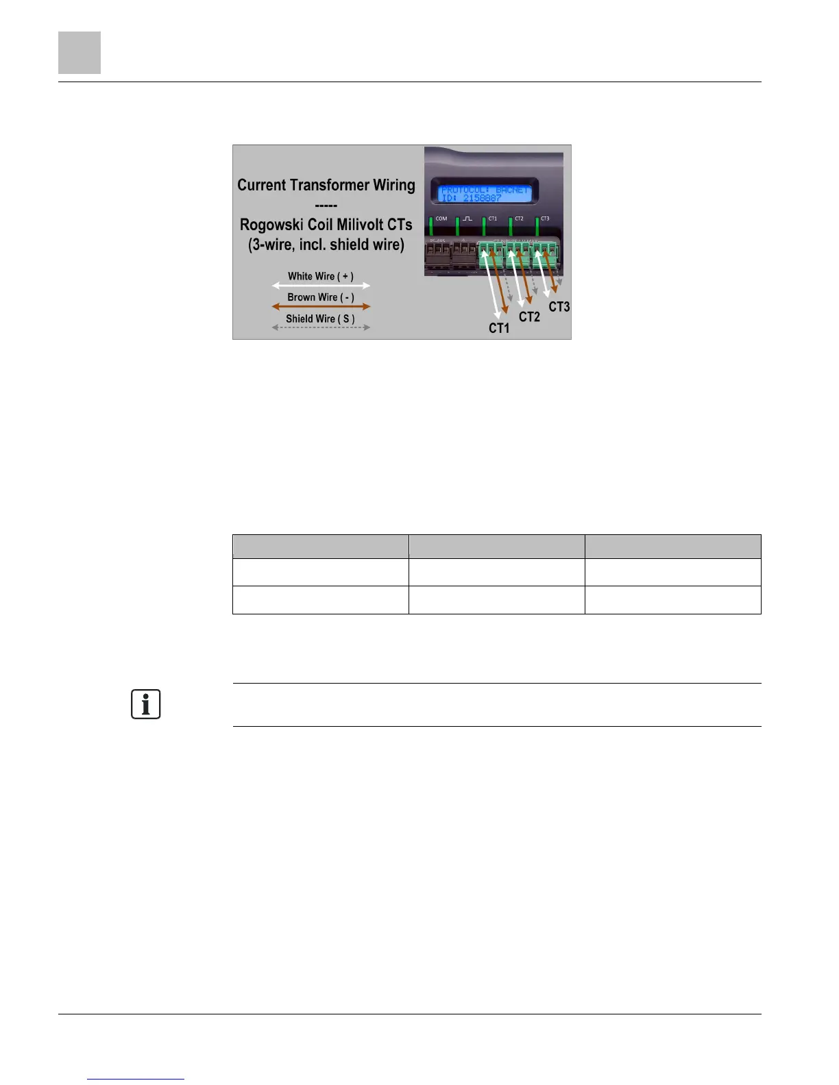
To connect the CT's wires to the terminals on the MD-BMS or MD-BMED:
1. Connect the CT's brown wire to the negative terminal on the connector.
2. Connect the CT's white wire to the positive terminal on the connector.
3. Connect the bare shield wire from the Rogowski Coil to the “S” shield terminal that
is part of the connector. This reduces interference and improves the accuracy of
the CT.
CT Wire Lead Polarity
Table 13: CT Polarity.
CT Type CT Lead + CT Lead -
Rogowski Coil* White Brown
Split Core mV White Black
* Rogowski Coils have a shield wire that must be connected to the meter. This reduces
interference and improves the accuracy of the CT.
The directionality for Rogowski Coil CTs is that the arrow points t
example, motor).
Connecting the Voltage
1. Connect the voltage leads (L1, L2, and L3, as necessary) to a circuit breaker. A
voltage lead of 14 AWG THHN Minimum 600 Vac rating (or equivalent, to maintain
600 Vac safety rating of the device) is required.
2. Connect the meter's L1, L2, and L3 leads to the circuit breaker or fuses.
3. See
Wiring Diagrams
for wiring connection specifics. Follow local electrical codes
during installation.