Prepping for Installation
31
Building Technologies 125-202
06/06/2017
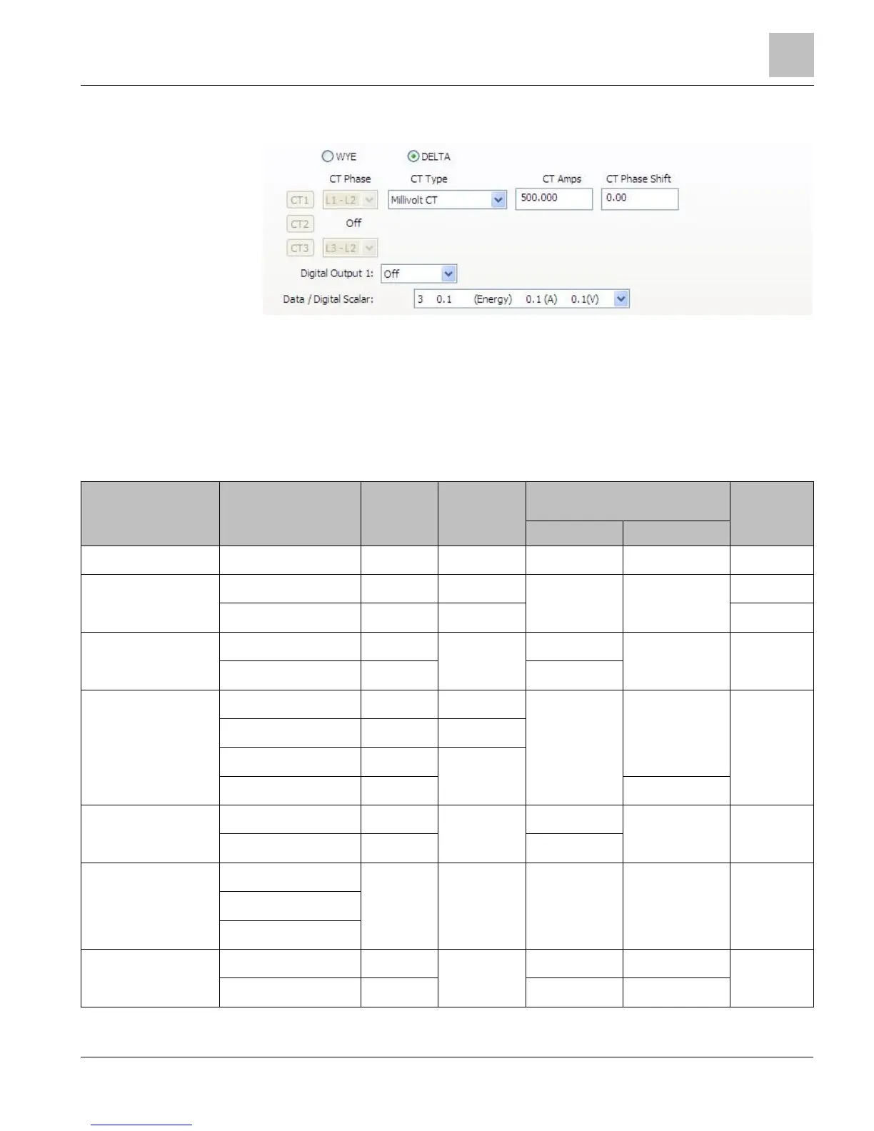
A DELTA connection displays only the two available CTs. Any changes made to CT1
also apply to CT3.
● Depending on the wiring connection, make changes to CT1, CT2, and/or CT3.
● CT Phase—Shows the voltage of the referenced CT.
● CT Type—Use the drop-down list to select the type of CT attached to the MD-BMS
or MD-BMED Power Meter.
● CT Amps—Enter the amperage rating.
● CT Phase Shift—Enter (in degrees) the phase shift of the CT. The default is 1.1.
Table 6: Current Transformers Setup Criteria.
CT Style Part Number CT Rated
Amps
CT Phase Shift
Value
Recommended Data/Digital Scalar for
3-Phase Loads
Nominal CT
Accuracy
230V 460V
Hinged Mini SCT-HSC-0050-U 50 0.75° Scalar 1 Scalar 2 0.5%
Hinged Midi SCT-HMC-0100-U 100 0.12° Scalar 2 Scalar 2 0.3%
SCT-HMC-0200-U 200 0.30° 1%
Split Core Small SCT-SCS-0050 50 2.20° Scalar 1 Scalar 2 1%
SCT-SCS-0100 100 Scalar 2
Split Core Medium SCT-SCM-0100 100 1.75° Scalar 2 Scalar 2 1%
SCT-SCM-0200 200 1.50°
SCT-SCM-0400 400 1.30°
SCT-SCM-0600 600 Scalar 3
Split Core Large SCT-SCL-0600 600 0.00° Scalar 2 Scalar 3 1%
SCT-SCL-1000 1000 Scalar 3
Rogowski Coils SCT-R16-A4-U 4000 N/A Scalar 3 Scalar 3 1.2%
SCT-R24-A4-U
SCT-R36-A4-U
Revenue Grade Toroidal
Solid Core
SCT-RGT12-0005-U 5 0.00° Scalar 1 Scalar 2 0.2%
SCT-RGT12-0020-U 20 Scalar 1 Scalar 2