24/72
Building Technologies User Manual OCI600 74 319 0002 0 c
HVAC Products Local setting up 15.07.2005
3 Local setting up
3.1 Mounting and electrical
installation
3.1.1 Mounting
All devices mentioned below must be mounted as explained
in the Mounting Instructions supplied with the relevant prod-
ucts.
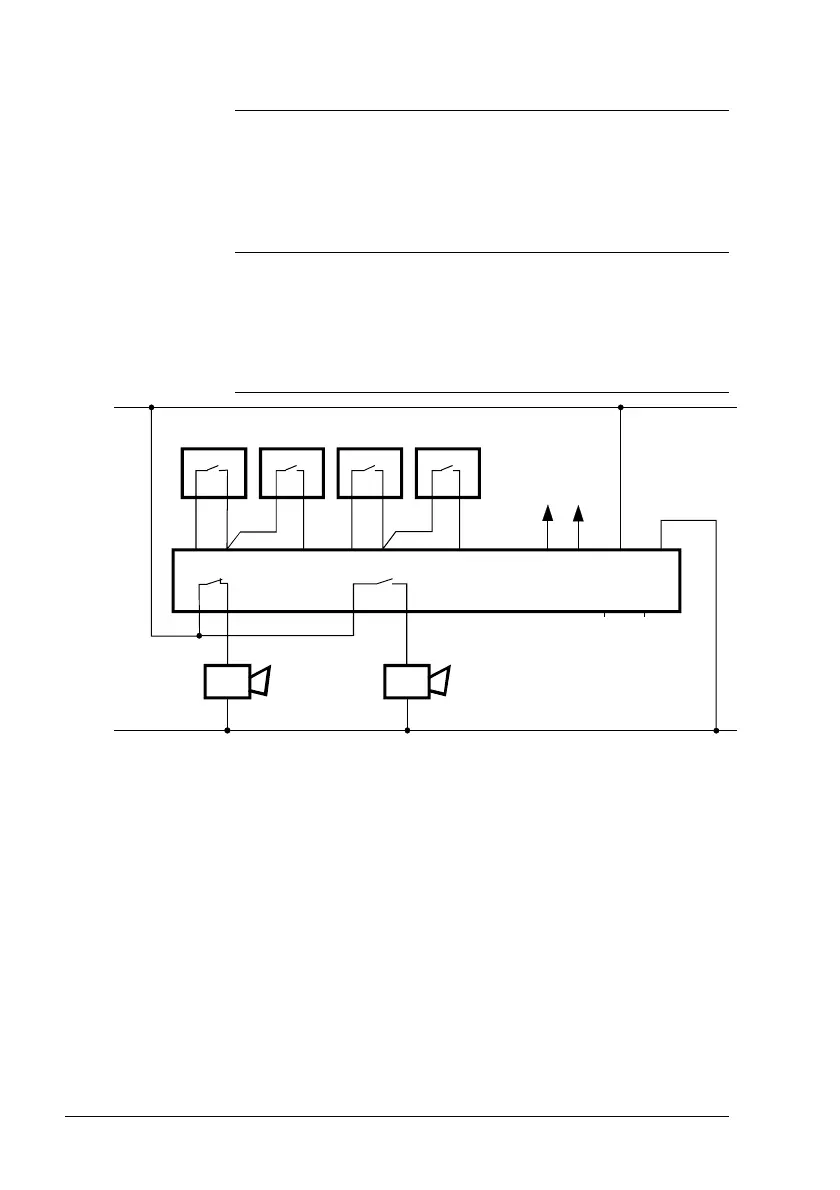
3.1.2 Connection diagram
H1
P1
PM
G1
P2 P3
P4
PMMP MP
P1 M P2 P3 M P4
MB DB G1 G2
H12
S13 S14 J1 J2
M
D
N1
G2
H2
2529A01
AC 24 V
LPB
H1
1
Devices
H1, H2 Alarm device
P1...P4 Devices with potential-free output
N1 Central communication unit OCI600
Connection terminals of the OCI600
G1, G2 Operating voltage AC 24 V
DB, MB LPB (data, ground)
P1...P4, M Status or alarm inputs
H11, H12 Relay output
S13, S14 Relay output
J1, J2, D Without function
LPB Local Process Bus
Note



 To Next Page